
Laser gas detection method with automatic linearity correction function

A linear correction, laser gas technology, applied in the direction of color/spectral characteristic measurement, etc., can solve the problems of increasing the workload of the staff, changing the performance of the detection device, hidden safety hazards, etc., to extend the manual correction period, ensure stability, and realize automatic The effect of correction

Active Publication Date: 2013-07-10
CHINA COAL TECH & ENG GRP CHONGQING RES INST CO LTD
View PDF8 Cites 9 Cited by
  • Summary
  • Abstract
  • Description
  • Claims
  • Application Information

AI Technical Summary

Problems solved by technology

[0004] Among the currently used laser gas detection methods and detection devices, the laser gas detection devices are all installed in mines with complex environments, and the detection devices are easily affected by various environmental factors, resulting in changes in their performance and inaccurate measurements. This requires mine staff to enter the site from time to time for equipment maintenance and overhaul, which not only increases the workload of the staff, but also easily creates certain hidden dangers

Method used


Image

  • Laser gas detection method with automatic linearity correction function
  • Laser gas detection method with automatic linearity correction function

Examples


Embodiment Construction

[0017] The preferred embodiments of the present invention will be described in detail below with reference to the accompanying drawings.

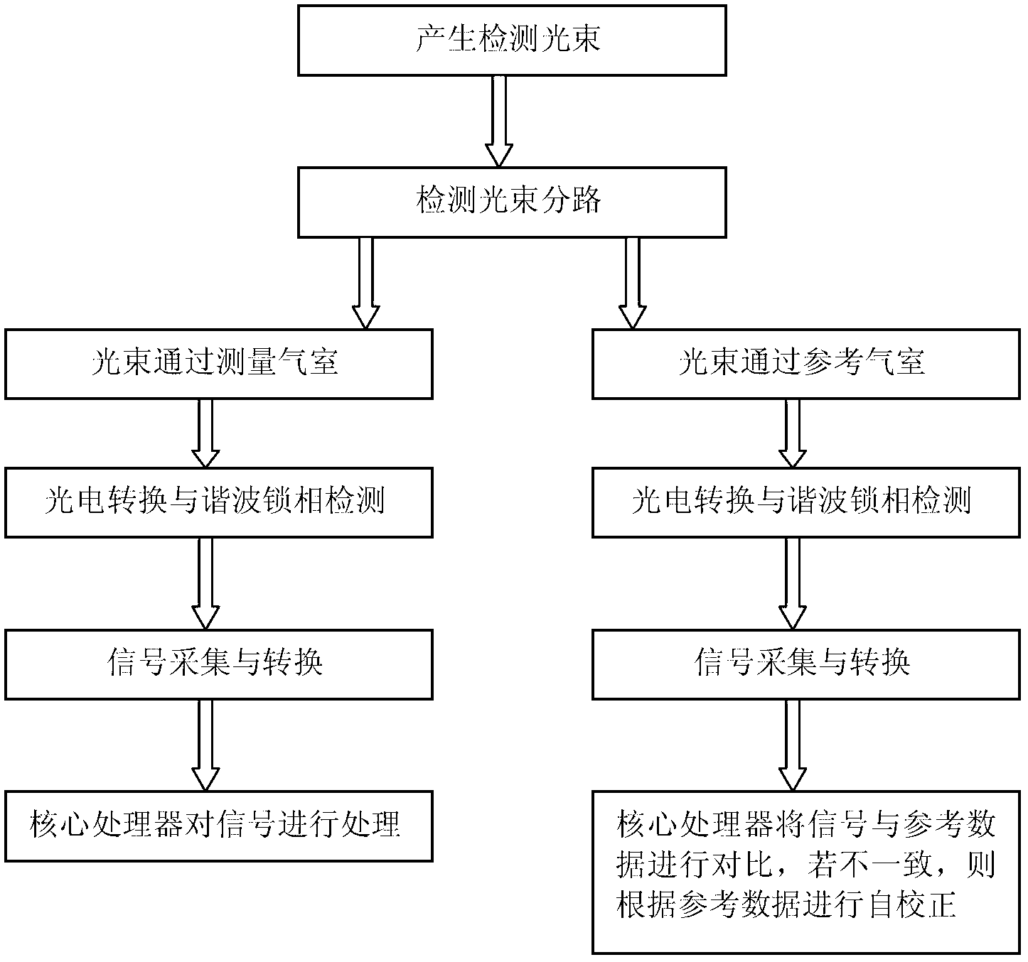
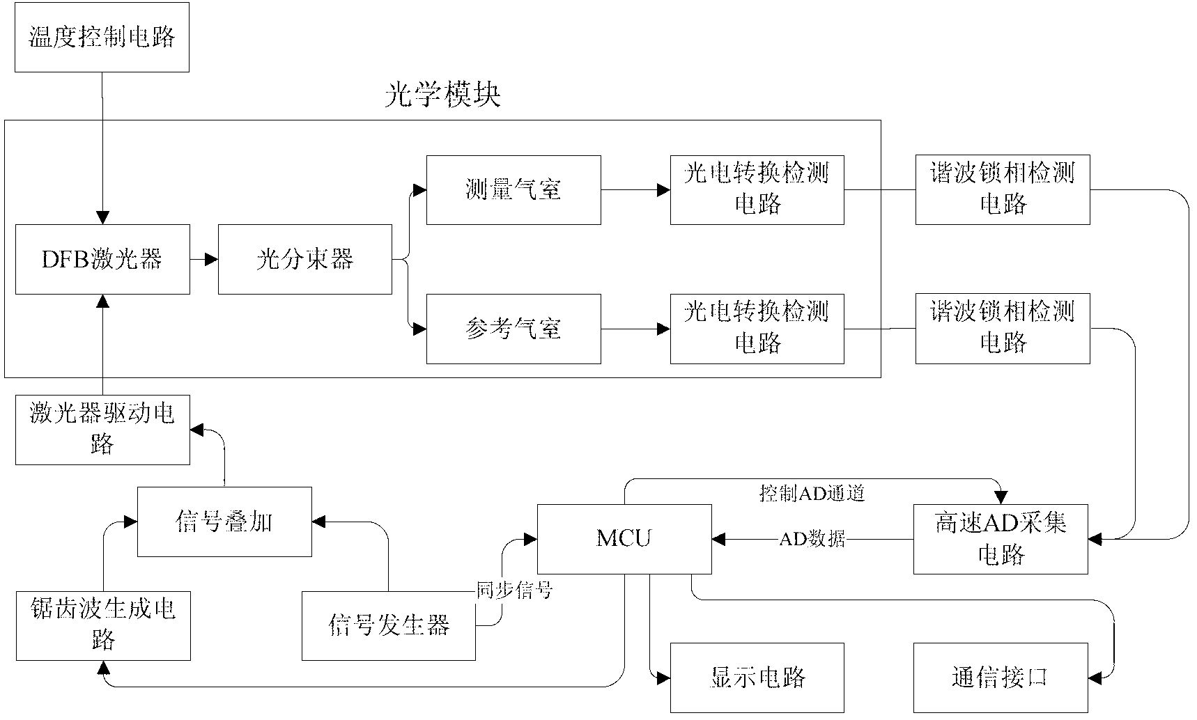
[0018] figure 1 As the flow chart of this detection method, as shown in the figure, the laser gas detection method with automatic linear correction function according to the present invention includes the following steps: Step 1: use a laser to generate a detection light source, and the monochromatic beam output by the laser is used as the detection beam ; Step 2: Split the detection beam in step 1. In this embodiment, a fiber optic splitter is used to divide the detection beam into two paths; Measuring the gas chamber, send another beam into the reference gas chamber with known concentration gas, and record the known concentration value and the laser center wavelength position after the first linear calibration as reference data; Step 4: From the measuring gas The two beams from the reference chamber and the reference gas chamber are resp...


PUM


Abstract

The invention discloses a laser gas detection method with an automatic linearity correction function, and belongs to the field of mining industry gas concentration measurement. The method comprises the following steps of: generating a detection light beam, branching the detection light beam, enabling the branched light beams to pass through a measuring air chamber and a reference air chamber, carrying out photovoltaic conversion and harmonic wave phase locking detection, then carrying out collecting and converting and finally sending the treated light beams into a core processor; for a signal generated by the light beam passing through the reference air chamber, comparing a detected gas concentration value and a central wavelength position with two reference data values recorded during calibration at the first time by the core processor, and if the values are different, starting a linearity correction algorithm, and correcting the device; and for a signal generated by the light beam through the measuring air chamber, displaying and sending by the core processor according to a detected gas concentration value. The method provided by the invention can accurately measure gas concentration in a mine and can realize the automatic correction in a detection process, thus the underground maintaining times for workers are reduced.

Description

technical field [0001] The invention belongs to the technical field of industrial and mining gas concentration measurement, and relates to a laser gas detection method with an automatic linear correction function. Background technique [0002] At present, the domestic and foreign methods for gas concentration detection in coal mines mainly include carrier catalysis, thermal conductivity, optical interference, and infrared detection. The method of carrier catalysis for gas concentration detection has the possibility of sulfide poisoning, and the detection range is narrow and the adjustment cycle is short; the use of thermal conductivity principle to detect gas concentration has low measurement accuracy, is greatly affected by ambient temperature, and is not easy to compensate, etc. Disadvantages: The optical interferometer uses the interference phenomenon of light to measure the gas concentration in the mine. Due to the complex design of the interferometric system, the cost i...

Claims


Application Information

Patent Timeline
Patent Type & Authority Applications(China)
IPC IPC(8): G01N21/31
Inventor 莫志刚孙世岭郭清华张书林李军龚仲强于庆
Owner CHINA COAL TECH & ENG GRP CHONGQING RES INST CO LTD
Learn More