
Radar wave form design method restrained by autocorrelation, orthogonality and Doppler tolerance

A technology of Doppler tolerance and radar waveform, applied in the field of radar waveform design

Inactive Publication Date: 2015-02-25
BEIJING INSTITUTE OF TECHNOLOGYGY
View PDF2 Cites 0 Cited by
  • Summary
  • Abstract
  • Description
  • Claims
  • Application Information

AI Technical Summary

Problems solved by technology

[0005] The ideal transmit waveform is that the respective matched filter outputs should have sufficiently low sidelobes (autocorrelation characteristics), and the waveforms should be orthogonal to each other to meet the requirements of instantaneous full polarization measurement (cross-correlation characteristics). At the same time, each waveform should Doppler tolerance is as large as possible (matched filters used for pulse compression cannot be too sensitive to frequency shifts), but there has not been a waveform design method that takes into account autocorrelation, cross-correlation, and Doppler Le Tolerance Three-Aspect Constraints

Method used


Image

  • Radar wave form design method restrained by autocorrelation, orthogonality and Doppler tolerance
  • Radar wave form design method restrained by autocorrelation, orthogonality and Doppler tolerance
  • Radar wave form design method restrained by autocorrelation, orthogonality and Doppler tolerance

Examples


Embodiment Construction

[0025] In order to better understand the technical solution of the present invention, the present invention will be further described in detail below in conjunction with the accompanying drawings and specific embodiments.

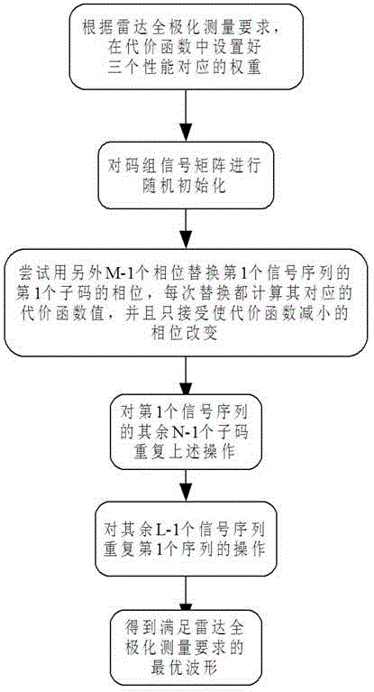
[0026] The invention provides a radar waveform design method, the process is as follows figure 1 As shown, the basic idea is to design a cost function with stable performance that comprehensively considers the three requirements of waveform autocorrelation, cross-correlation and Doppler tolerance. These three performances are constrained by their respective weighting coefficients in the cost function. The performance of the waveform can be controlled by changing the relative value of each weighting coefficient in the cost function; then the Greedy random search optimization algorithm is used to design a quadrature phase-modulated waveform sequence with any phase and length that meets the requirements of radar full-polarization measurement. details as follow...


PUM


Abstract

The invention discloses a radar waveform design method restrained by autocorrelation, orthogonality and Doppler tolerance. Firstly, a cost function with stable properties and with overall consideration of the autocorrelation, the cross correlation and the Doppler tolerance of wave forms is designed. Secondly, by using a Greedy random search optimization algorithm, repeated iterations are carried out until a system no longer receives any phase change, and the wave form design meeting the requirements of the full polarization measurement of radar is obtained.

Description

technical field [0001] The invention relates to the field of radar waveform design, in particular to a radar waveform design method under constraints of autocorrelation, orthogonality and Doppler tolerance. Background technique [0002] In the process of electromagnetic wave propagation, the way in which the spatial orientation of the electric field vector at a fixed point in space changes with time is called polarization. The target is equivalent to a variable polarizer, and its polarization information can represent all the information of its scattering characteristics, so the use of polarization information can improve the performance of radar target detection, tracking and identification. The use of polarization technology is also beneficial to ground / sea clutter suppression. The premise of the utilization of polarization information is that the radar has the capability of polarization measurement. Instantaneous full-polarization measurements require horizontally polar...

Claims


Application Information

Patent Timeline
Patent Type & Authority Patents(China)
IPC IPC(8): G01S7/02
Inventor 傅雄军王琳高梅国史陆敏王才赵会朋李婷杨伟杰
Owner BEIJING INSTITUTE OF TECHNOLOGYGY
Learn More