
Target location extraction method applicable to through-the-wall radar imaging

A technology of through-wall radar and target location, which is applied in the field of image processing, and can solve problems such as low threshold setting, reduction of signal-to-noise ratio of target image, and inability to extract multiple target positions.

Inactive Publication Date: 2013-07-10
UNIV OF ELECTRONICS SCI & TECH OF CHINA
View PDF6 Cites 19 Cited by
  • Summary
  • Abstract
  • Description
  • Claims
  • Application Information

AI Technical Summary

Problems solved by technology

For the above two methods based on fixed threshold detection, it is difficult to extract the target position well in the case of multiple targets. If the threshold is set too high, it is easy to cause the loss of weak and small targets; Wave noise creates false targets
The Italian SELEX scientific research institution extracts the position of the pixel unit corresponding to the maximum pixel value in the target image as the target position. This method can only extract a single target position, and cannot achieve multiple target positions. The practicability is poor
[0004] When performing through-wall imaging of multiple concealed targets in complex buildings, the difference between different targets and the isolation wall of the through-wall radar will cause a significant gap in the intensity of the target image. At the same time, the wall penetration attenuation and the multipath Clutter will reduce the signal-to-noise ratio of the target image, so it is difficult for existing methods to effectively extract the location information of multiple targets

Method used


Image

  • Target location extraction method applicable to through-the-wall radar imaging
  • Target location extraction method applicable to through-the-wall radar imaging
  • Target location extraction method applicable to through-the-wall radar imaging

Examples


Embodiment Construction

[0036] The specific implementation manner of the present invention is given below in conjunction with a typical example.

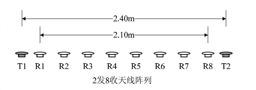
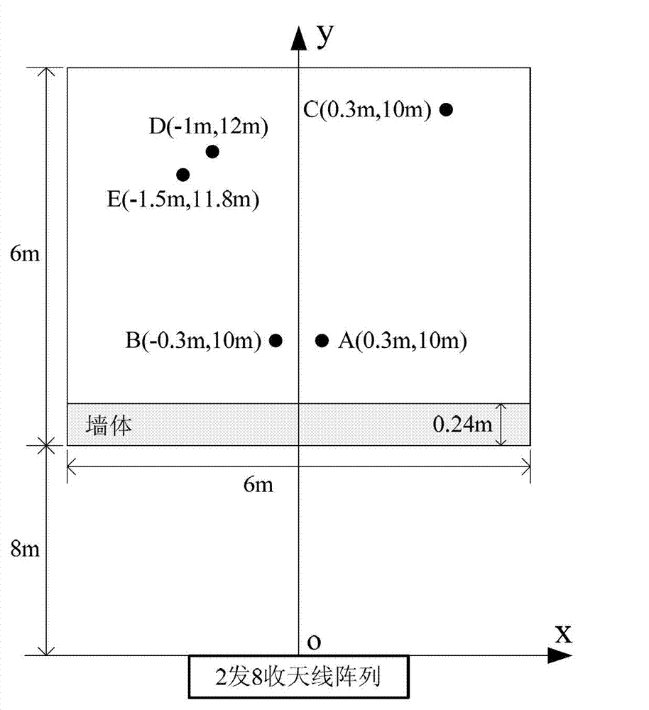
[0037] In the simulation setting, the through-the-wall radar adopts an antenna array with two transmitters and eight receivers, and the array layout is as follows: figure 2 As shown, the transmit antenna array aperture is L T =2.4m, the receiving antenna array aperture is L R =2.1m. The two transmitting antennas sequentially transmit step-frequency continuous wave signals, the signal frequency range is 1GHz-2GHz, and the step interval is 2MHz, including 501 frequency points in total. Simulation scenarios such as image 3 As shown, the antenna array is 8m away from the wall, the thickness of the wall is 0.24m, and the dielectric constant of the wall is 9.

[0038] The simulation sets 5 targets at A (0.3m, 10m), B (-0.3m, 10m), C (2.0m, 13m), D (-1.0m, 12m), E (-1.5m, 11.8m) , each target echo signal-to-noise ratio is set to -18dB, -18dB, -25dB, -18dB,...


PUM


Abstract

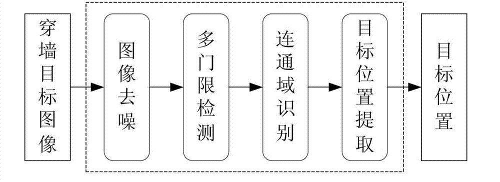
The invention discloses a target location extraction method applicable to through-the-wall radar imaging, belongs to the technical field of image processing, and particularly relates to through-the-wall radar imaging techniques. According to an image formed by a back wave of through-the-wall radar, firstly, high-frequency noisy points in the image are inhibited through a two-dimensional low pass filter, then, a plurality of detection thresholds with reasonable layouts are adopted, binaryzation detection is carried out on the target image, then, connected domains in the image after the detection are searched and used as possible target areas, the connected domains under the various thresholds are classified according to target subordinating relations, finally, occurrence numbers of the corresponding connected domains of various targets are arrayed, the corresponding connected domains with large numbers are selected, and statistical averages of all pixel unit locations in the connected domains are used as target location coordinates. According to the target location extraction method applicable to the through-the-wall radar imaging, accurate location coordinates of a plurality of targets comprising adjacent targets and dim targets can be steadily extracted in the target image with a low through-the-wall signal to clutter ratio and a low through-the-wall signal to noise ratio, and accurate target location based on the through-the-wall radar imaging is achieved.

Description

technical field [0001] The invention belongs to the technical field of image processing, and relates to radar imaging technology, in particular to the through-wall radar imaging processing technology. Background technique [0002] The research on through-wall radar imaging technology mainly includes building layout imaging and hidden target imaging, which are used to form building layout panoramic images and hidden target images respectively. The panoramic image of the building layout contains images of all the walls of the building, which can be used as a reference to determine the relative position of the hidden target in the building. The hidden target image is mainly used to determine the position, type and state of the target, and the most basic function is to determine the target position. Therefore, the basic problem of the hidden target imaging is how to extract the position information of the target from the target image. [0003] Aiming at the basic problems of ta...

Claims


Application Information

Patent Timeline
Patent Type & Authority Applications(China)
IPC IPC(8): G01S7/41
Inventor 孔令讲贾勇刘剑刚杨晓波
Owner UNIV OF ELECTRONICS SCI & TECH OF CHINA
Learn More