Active radio frequency identification device (RFID) positioning card reader based on micro-strip array directing antenna array positioning

A technology for directional antennas and microstrip antennas, which is applied in the direction of antenna support/installation devices, instruments, and collaborative work devices, etc., and can solve problems such as unseen applications, unobtainable, and large environmental impacts

Inactive Publication Date: 2013-07-10
THE THIRD RES INST OF MIN OF PUBLIC SECURITY
View PDF6 Cites 6 Cited by
  • Summary
  • Abstract
  • Description
  • Claims
  • Application Information

AI Technical Summary

Problems solved by technology

[0003] The existing RFID card positioning technology mainly has the following types: one is to use the very short reading and writing distance of the passive RFID card, the distance is only about tens of centimeters, if the position of the card reader is known, the card can be read Make sure that the card is nearby, but this is only point information, and the trajectory between this reading and the next reading cannot be obtained. A very large number of card readers are required to locate the area in detail, so this method only has some special applications
The second is to use many active RFID card readers that can measure the strength of radio frequency signals to be evenly arranged in an area. The communication distance between the active RFID card and the card reader can reach more than tens of meters. After multiple distance-measuring card readers are arranged at a certain position, the incoming active RFID card can be read by several card readers at the same time and the signal amplitude of the card can be measured at the same time, because the square root of the signal amplitude The value is inversely proportional to the straight-line distance between the two. Each card reader can calculate the straight-line distance from the card according to the signal amplitude. Can calculate the spatial position of this card; this method is greatly affected by the environment, and may be effective in large open spaces. In small rooms and areas with metal parts, the electromagnetic wave will be interfered by the mirror image of the surrounding metal and walls, reflected, Due to factors such as diffraction, penetration attenuation, and amplitude fluctuations, the corresponding distance of the measured signal amplitude may be seriously inaccurate, and the resulting positioning error may be several meters or greater.
The third method is to arrange an active RFID card reader that can accurately measure the signal amplitude in an area (room), and then evenly arrange many similar active RFID cards that determine the position. There is a certain corresponding signal amplitude in the card reader. When an active RFID card to be positioned enters this area, the signal sent by it is received by the card reader and the received signal amplitude is measured. The card reader takes this The amplitude is compared with the signal amplitude of the auxiliary card arranged at a certain position and calculated to obtain the spatial position in this area or indoor; this method improves the reference basis for estimating the distance of the received signal, but it is still affected by the spatial distribution of walls, facilities, etc. , Metal objects and people carrying RFID cards interfere with the amplitude of electromagnetic waves, which makes the received signal amplitude different from the position reference amplitude and is relatively inaccurate. The distance distribution does not follow the calculation relationship and causes errors. The resulting error will be 3 meters. above
Other positioning methods include the developing digital signal ranging technology for positioning, but since the RFID technology is characterized by very cheap RFID cards, the complexity and cost of the card will be greatly increased after digital ranging is added, which deviates from the promotion of RFID technology. purpose, has not yet seen the application

Method used


Image

  • Active radio frequency identification device (RFID) positioning card reader based on micro-strip array directing antenna array positioning
  • Active radio frequency identification device (RFID) positioning card reader based on micro-strip array directing antenna array positioning
  • Active radio frequency identification device (RFID) positioning card reader based on micro-strip array directing antenna array positioning

Examples


Embodiment Construction

[0025] In order to make the technical means, creative features, goals and effects achieved by the present invention easy to understand, the present invention will be further described below in conjunction with specific illustrations.

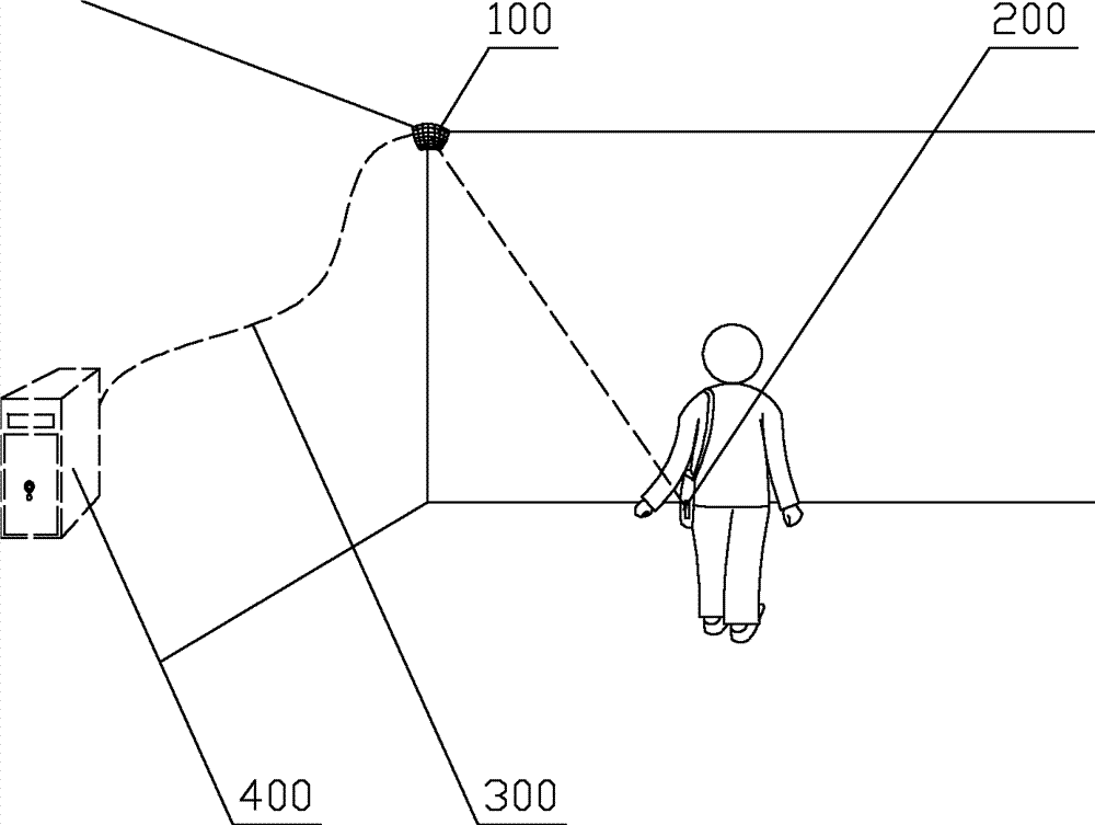
[0026] like figure 1 As shown, the system environment used by the microstrip secondary array narrow-angle pointing antenna array active RFID positioning card reader based on antenna array scanning positioning of the present invention is provided in the figure, it is composed of a microstrip secondary array narrow-angle Pointing to the antenna array active RFID positioning card reader 100, the object of use is the active RFID card 200 that uses the UHF carrier high-frequency compression transmission information carried by walking people or low-speed moving objects, and the RFID system network 300 and the server of the RFID system Composed with database 400 .

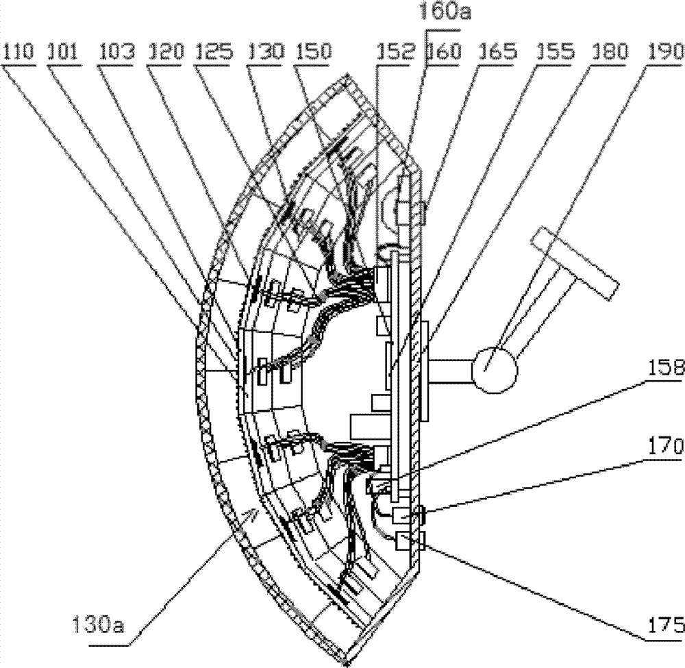
[0027] see figure 2 , the microstrip secondary array narrow-angle pointing antenna a...


PUM


Abstract

The invention discloses an active radio frequency identification device (RFID) positioning card reader based on a micro-strip secondary array narrow-angle directing antenna array of directing antenna array positioning. The active RFID positioning card reader comprises an antenna and a card reading processing device, wherein the antenna and the card reading processing device are in signal connection, and the antenna is the micro-strip secondary array antenna array. The micro-strip secondary array antenna array is divided into a plurality of narrow solid angle micro-strip array narrow-angle directing antennas, and the plurality of narrow solid angle micro-strip array narrow-angle directing antennas is used for receiving an active RFID card signal of ultrahigh frequency carrier high frequency compression sent information carried by an ambulatory human or a low-speed moving object to carry out positioning card reading. The active RFID positioning card reader is suitable for carrying out the positioning card reading on an active RFID card which is capable of sending information with moderate transmitted power and an ultrahigh frequency carrier in a higher frequency compression mode in a certain range of space. A single active RFID positioning card reader is used, direction and corresponding position of the RFID card in a certain area can be confirmed, and more than two positioning card readers are used to read a card in a networking cross mode, the position of the active RFID card can be confirmed accurately, or a range of positioning card reading can be expanded.

Description

technical field [0001] The invention relates to a microstrip secondary array narrow-angle pointing antenna array active RFID positioning card reader based on pointing antenna array positioning, which adopts a microstrip array antenna in the UHF band to achieve narrow-angle pointing reception, and adopts a spatial solid angle vertically and horizontally Distributed directional antenna arrays, corresponding receiving chip arrays and embedded computer processing control read active RFID card information and calculate and determine the coordinate position of the card, which belongs to the field of information technology RFID positioning. Background technique [0002] In today's society, RFID technology has been widely used in people's lives, as identity documents, deduction certificates, access cards, product identity and parameter prompt labels, environmental information perception transmitters after adding sensors, proximity Bluetooth, and away from warning devices, etc. The m...

Claims


Application Information

Patent Timeline
Patent Type & Authority Applications(China)
IPC IPC(8): G06K7/10G06K17/00H01Q1/22
Inventor 朱弘江洪洪利军赵锐陈勇疏天民
Owner THE THIRD RES INST OF MIN OF PUBLIC SECURITY
Why Eureka
Try Eureka