Receiving-end power grid dynamic reactive power compensation equipment configuration position selecting method

A receiving-end power grid and compensation device technology, which is applied in reactive power compensation, reactive power adjustment/elimination/compensation, etc., can solve the problems of expensive dynamic reactive power compensation device equipment, difficult to be widely used, and large-capacity adoption

Inactive Publication Date: 2013-07-10
HUNAN UNIV
View PDF2 Cites 30 Cited by
  • Summary
  • Abstract
  • Description
  • Claims
  • Application Information

AI Technical Summary

Problems solved by technology

The cost of dynamic reactive power compensation equipment is expensive, but the configuratio

Method used


Image

  • Receiving-end power grid dynamic reactive power compensation equipment configuration position selecting method
  • Receiving-end power grid dynamic reactive power compensation equipment configuration position selecting method
  • Receiving-end power grid dynamic reactive power compensation equipment configuration position selecting method

Examples


Embodiment Construction

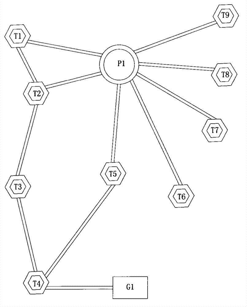
[0035] Such as figure 1 The regional power grid system shown is a geographical wiring diagram of an actual power grid. As the research receiving end regional power grid of the present invention, it includes a 500KV balanced station P1 and nine 220KV PQ nodes, numbered T1~T9 respectively. The system parameters are shown in the table below; 1 power station G1, generating power: 600+j204; the system is studied under the maximum operating mode in summer.

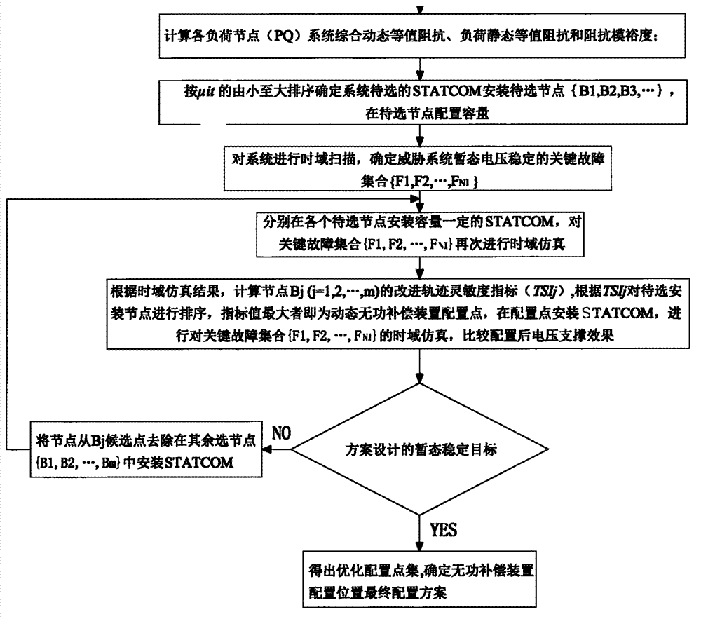
[0036] Attached below figure 2 Shown case, the inventive method is described in detail:

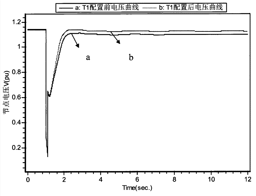
[0037] (1) Use the power system comprehensive simulation analysis (PSD-BPA software) to fill in the LI card settings in the stability file to conduct time-domain simulation analysis of the scene where the load in the study area continues to increase by 5% within t=12s, including a total of 9 PQ nodes , determine the PQ nodes to be investigated as {T1, T2, ..., T9}, record the number of the i-th PQ node as i, sort out the data of the volt...


PUM


Abstract

The invention discloses a receiving-end power grid dynamic reactive power compensation equipment configuration position selecting method. Receiving-end power grid dynamic reactive power compensation equipment configuration position selection is based on an electric system safety and stability and dynamic voltage support quantitative analysis method and reflects a combined influence of configuration positions to a system according to a system voltage stability margin and a support effect. The method overcomes the influence that a static configuration method cannot reflect system disturbance, comprehensively and fully reflects an improving effect of dynamic reactive power compensation equipment configuration stations to system safety and stability characters, and sufficiently plays dynamic reactive power compensation equipment roles, and therefore, the receiving-end power grid dynamic reactive power compensation equipment configuration position selecting method has a good actual guiding significance.

Description

technical field [0001] The invention belongs to the technical field of electric power system and automation thereof, and proposes a method for selecting a configuration position of a dynamic reactive power compensation device of a receiving-end power grid. Background technique [0002] With the increasing complexity of the power system and the rapid growth of the load level, the voltage stability of the power grid at the receiving end has received more and more attention. The Flexible AC Transmission System (FACTS) technology based on high-power power electronics is widely used in the power industry to enhance the stability and safety of power system operation, improve power transmission capacity and power efficiency, save energy and improve power Quality and other aspects are playing an increasingly important role. Compared with traditional reactive power compensation equipment, dynamic reactive power compensation devices represented by static var compensator (static var c...

Claims


Application Information

Patent Timeline
IPC IPC(8): H02J3/18
CPCY02E40/30
Inventor 李帅虎曹一家辛拓杨银国林建熙范丁中
Owner HUNAN UNIV
Why Eureka
Try Eureka