Light emitting diode (LED) luminous device directly driven in constant current by alternating current

A technology of constant current drive and lighting device, which is applied in the direction of electric light source, lighting device, lamp circuit layout, etc., to achieve the effect of prolonging service life, reducing power loss and small size

Active Publication Date: 2013-07-10
四川能投智慧光电有限公司
View PDF9 Cites 4 Cited by
  • Summary
  • Abstract
  • Description
  • Claims
  • Application Information

AI Technical Summary

Problems solved by technology

[0007] The technical problem to be solved by the present invention is to provide an LED lighting device directly driven by alternating current with a constant current in order to solve the problem in the prior art that the LED lighting device is directly driven by alternating current.

Method used


Image

  • Light emitting diode (LED) luminous device directly driven in constant current by alternating current
  • Light emitting diode (LED) luminous device directly driven in constant current by alternating current
  • Light emitting diode (LED) luminous device directly driven in constant current by alternating current

Examples


Embodiment 1

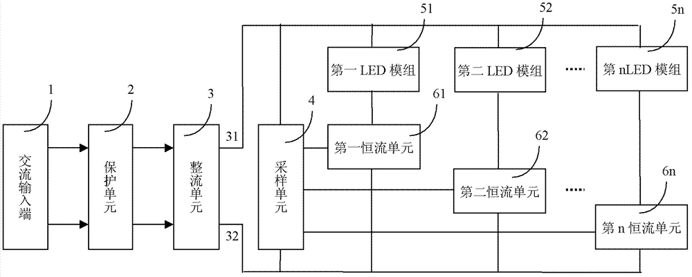
[0044] Such as figure 2 As shown, the protection unit 2 in this example is composed of a fuse F and a varistor VR. The fuse F is connected in series to the phase line L of the AC input terminal 1, and the varistor VR is connected in parallel to the phase line L and the neutral line N of the AC input terminal 1. between. The protection unit 2 is connected to the rectification unit 3 formed by the full-wave rectification circuit D1, and the output end of the rectification unit 3 is connected in parallel with 4 branches.

[0045] The first branch is composed of the first LED module and the first constant current unit in series. The first LED module is composed of one LED11, the positive end of which is connected to the positive pole of the rectification circuit D1, and the negative end is connected to the rectification circuit through the first constant current unit. D1 negative pole. In this example, the sampling is composed of a resistor network, including resistors R1 ~ R8....

Embodiment 2

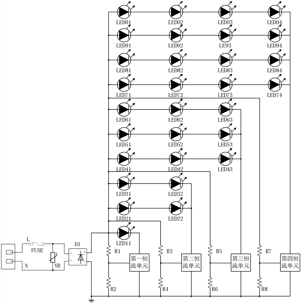
[0049] image 3 The schematic diagram of the circuit of this example is shown, and it can be seen that this example is the same as that of Example 1 except that the LED module structure and its connection method are different from Example 1. The following only describes the structure of the LED module with four branch circuits. For other structures and their working process, please refer to the description of Embodiment 1, which will not be repeated here. The first LED module in the first branch of this example is composed of one LED31, the positive terminal of the first LED module is connected to the positive pole of the rectifier circuit D1, and the negative terminal of the first LED module is connected to the rectifier circuit through the first constant current unit D1 negative pole. The second LED module in the second branch of this example includes 4 LEDs in total, LED31, LED32, LED21, and LED22. When the first constant current unit is turned off, these 4 LEDs form a 2×...

Embodiment 3

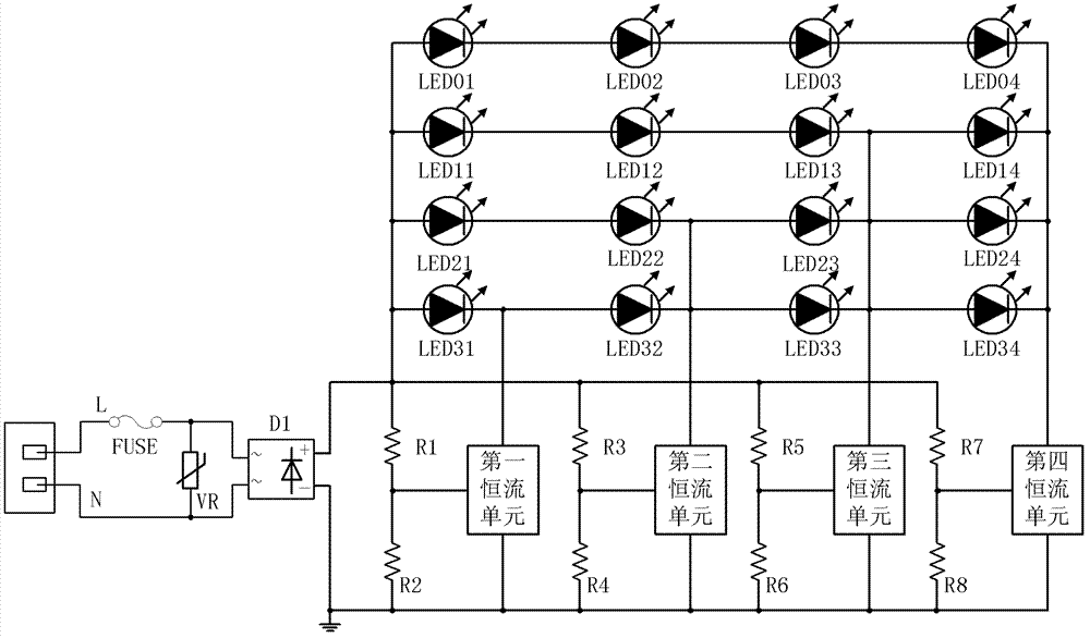
[0052] Such as Figure 4 As shown, the circuit schematic diagram of this example is compared with that of Example 2. The connection mode of each LED module has been further optimized. The four LED modules in the four branches are composed of 16 LEDs and adopt a 4×4 matrix topology. . The first LED module in this example is composed of a 1×4 array composed of 4 LEDs connected in parallel, namely LED01, LED11, LED21 and LED31. The second LED module in this example is composed of a 2×4 array composed of 8 LEDs connected in series and parallel, including LED01, LED11, LED21, LED31, LED02, LED12, LED22, and LED32. The third LED module in this example is composed of LED01, LED11, LED21, LED31, LED02, LED12, LED22, LED32, LED03, LED13, LED23, LED33, a total of 12 LEDs connected in series and parallel to form a 3×4 array. The LED module consists of LED01, LED11, LED21, LED31, LED02, LED12, LED22, LED32, LED03, LED13, LED23, LED33, LED04, LED14, LED24, LED34, a total of 16 LEDs are c...


PUM


Abstract

The invention relates to an alternating current direct constant current driving technology of a light emitting diode (LED) luminous device, discloses the LED luminous device directly driven in a constant current by an alternating current, and aims at the problem that the LED luminous device is directly driven by the alternating current in the prior art. The technical scheme includes that a parallel branch composed of n LED modules and a constant current unit connected in series is connected on the output end of a rectifying circuit, and cyclical flickering phenomenon caused by alternating voltage change can be avoided by setting current values, turn-off voltages and connecting voltages of branch constant current units. Because current of each branch is constant, LEDs in the LED modules can not cause current change because of change of junction temperature, and reliability is improved. Increasing of branch numbers enables a wave form of a driving current to approach a sine wave, and power factor and efficiency of the luminous device are improved through theory analysis.

Description

technical field [0001] The invention relates to an LED (light-emitting diode) light emitting device, in particular to an alternating current direct constant current driving technology of the LED light emitting device. Background technique [0002] As a new type of solid-state light source, LED is expected to become a new generation of lighting source due to its advantages of energy saving, environmental protection and long life. As we all know, almost all existing LEDs are driven by direct current, but our production and living electricity is alternating current. Therefore, in currently used LED products, a power converter is needed to convert AC power into DC power. The introduction of power converters brings many negative effects. First, the life of the power converter is much lower than the life of the LED itself, which shortens the service life of the lighting device; second, the power converter will reduce the efficiency of the lighting device; third, in low-power app...

Claims


Application Information

Patent Timeline
Patent Type & Authority Applications(China)
IPC IPC(8): H05B37/02
CPCH05B45/46
Inventor 李东明杨冕封正勇龙文涛赵昆张明
Owner 四川能投智慧光电有限公司
Why Eureka
Try Eureka