Rotary drum evaporator

A rotary evaporator and drum-type technology, applied in the field of rotary evaporators, can solve the problems of high-power motor waste, inability to enlarge equipment, time-consuming and labor-consuming water baths, etc., to simplify operation, improve heat exchange efficiency, and save water and electricity resource effect

Inactive Publication Date: 2013-07-17
SUZHOU CHIEN SHIUNG INST OF TECH
View PDF5 Cites 4 Cited by
  • Summary
  • Abstract
  • Description
  • Claims
  • Application Information

AI Technical Summary

Problems solved by technology

Due to the above situation, the whole equipment takes up a lot of space, adjusting the height of the water bath is time-consuming and labor-intensive, and the high-power motor also leads to unnecessary waste
And even after the above adjustments and changes, it is still impossible to further enlarge the equipment (the capacity of the evaporating flask is above 50L)

Method used


Image

  • Rotary drum evaporator
  • Rotary drum evaporator
  • Rotary drum evaporator

Examples


Embodiment approach 1

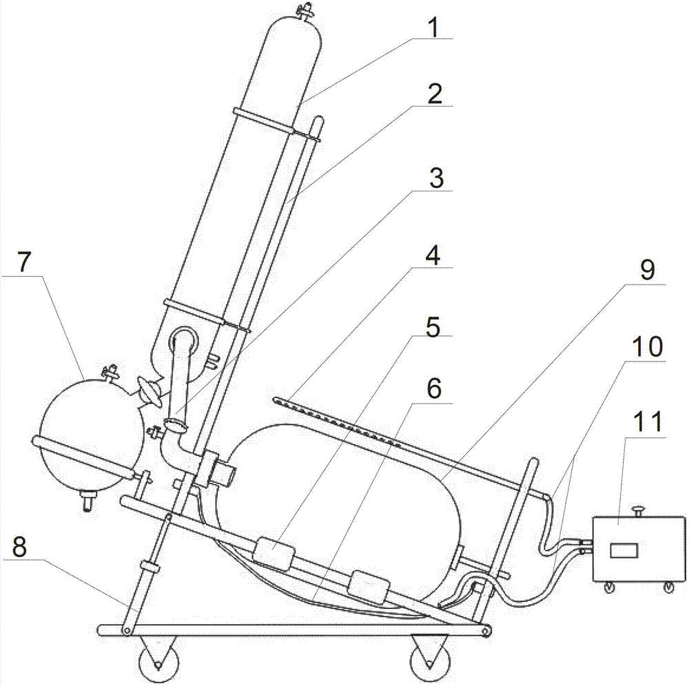
[0015] Implementation Option 1: If figure 1 As shown, a roller 5 is installed on the roller frame 8, and the roller 5 is driven by a speed-regulating motor, and the organic solution is placed in a rotating bottle 9, which is supported by the roller frame 8 and driven to rotate. After the circulating water is heated by the water bath 11, it flows out from the outlet end of the circulating water pipe 10 and sprays out from the nozzle of the nozzle 4, and the hot water flows down along the wall of the rotating bottle 9, and then is collected by the rotating bottle cover 6, and passes through the circulating water pipe The water inlet end of 10 flows back to the water bath, and through this cycle, the organic solution in the evaporating flask is continuously heated; when the organic solution is in a vacuum state, the rotation of evaporating flask 9 increases its evaporation area, thus vaporizing rapidly, resulting in The organic vapor enters the heat exchanger 1 along the sealing ...

Embodiment approach 2

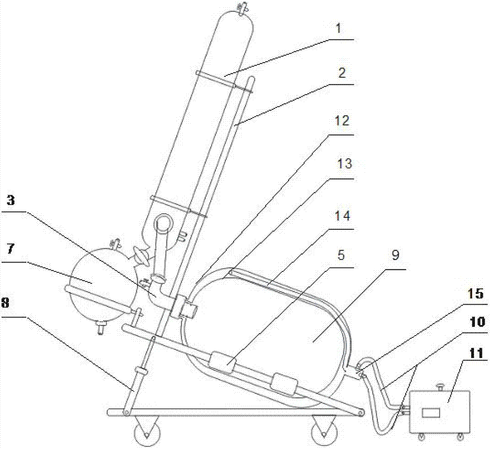
[0016] Implementation Option 2: If figure 2 As shown, a roller 5 is installed on the roller frame 8, and the roller is driven by a speed-regulating motor. The organic solution is placed in the evaporating bottle 9, which is supported by the roller frame 5 and driven to rotate. The evaporating bottle 9 has an outer bottle wall 12 and an inner wall. The double-layer structure of the layer bottle wall 13, and the lower end of the evaporating bottle 9 is provided with a double-channel rotary joint 15, and a section of pipeline 14 and a double-channel rotary joint 15 are arranged between the outer layer bottle wall 12 and the inner layer bottle wall 13. connected by a channel. After the circulating water is heated by the water bath 11, it flows out from the outlet end of the circulating water pipe 10 and enters the interlayer space formed by the inner and outer double walls of the evaporating bottle 9 along the double-channel rotary joint 15. When the water level reaches a certain...


PUM


Abstract

The invention discloses a rotary drum evaporator which comprises a water bath kettle, an evaporating flask, a heat exchanger, and a receiving flask. The water bath kettle, the evaporating flask, the heat exchanger and the receiving flask are connected in sequence. A seal mechanism is further arranged between the evaporating flask and the heat exchanger. The rotary drum evaporator further comprises a roller carrier. A rotary flask cover is fixed on the roller carrier. The evaporating flask is rotatably fixed on the roller carrier and disposed in the rotary flask cover. The roller carrier is capable of driving the rotary flask cover and the evaporating flask in mechanical drum rotation. According to the drum principle, the evaporating flask of the rotary drum evaporator is rotated to make the production of ultra-large rotary evaporators possible. The circulating hot water heating mode requires smaller equipment space, and the operation is simpler. The special design of the heat exchanger increases the heat exchange efficiency and further decreases equipment space. The rotary drum evaporator is compact in structure, low in power consumption, and convenient to operate, and saves water and electricity.

Description

technical field [0001] The invention relates to an evaporator, in particular to a rotary evaporator. Background technique [0002] The rotary evaporator is a device that uses a rotary evaporating bottle to increase the evaporation area. Under reduced pressure, it rotates while heating, so that the solution in the bottle diffuses and evaporates. The evaporated gas becomes liquid again after condensation. Through this process To achieve concentration, drying, recovery and other purposes. The small rotary evaporator commonly used in the laboratory fixes the evaporating bottle directly on the rotating mechanism, and the main force-bearing parts are the rotating mechanism and the bottleneck. If the large-scale equipment works on the same principle, due to the increase in the weight of the material in the evaporating bottle, the strength of the equipment is required to increase, so the wall of the evaporating bottle needs to be thickened, the rotating mechanism also needs to be e...

Claims


Application Information

Patent Timeline
Patent Type & Authority Applications(China)
IPC IPC(8): B01D1/00B01D1/30
Inventor 马荣华严丹红
Owner SUZHOU CHIEN SHIUNG INST OF TECH
Why Eureka
Try Eureka