MVR (Mechanical Vapor Recompression) continuous evaporative crystallization system and continuous evaporative crystallization method

A technology of evaporative crystallization and evaporator, applied in the field of MVR continuous evaporative crystallization system, can solve the problems of no significant advantage of MVR system, increased complexity of MVR system, fine crystal grain size, etc., and achieves small footprint, compact equipment, required small space effect

Active Publication Date: 2013-07-17
江苏迪飞生物技术有限公司
View PDF7 Cites 51 Cited by
  • Summary
  • Abstract
  • Description
  • Claims
  • Application Information

AI Technical Summary

Problems solved by technology

This leads to the poor crystallization effect of the existing mechanical vapor recompression continuous evaporation crystallization system, such as problems such as small crystal particle size
There are also some manufacturers who will add steam pipes t

Method used


Image

  • MVR (Mechanical Vapor Recompression) continuous evaporative crystallization system and continuous evaporative crystallization method

Examples


Embodiment 1

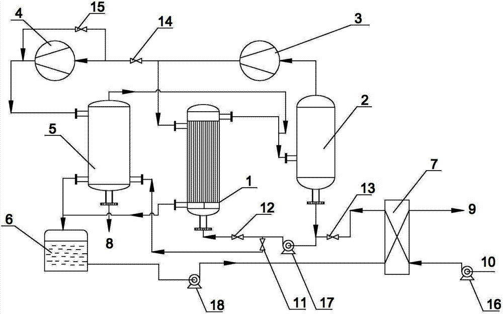
[0046] A MVR continuous evaporation and crystallization system, said system includes an evaporator 1, a vapor-liquid separator 2, a main water vapor compressor 3, an auxiliary water vapor compressor 4 and a crystallizer 5;

[0047] The outlet of the evaporator 1 is connected to the inlet of the vapor-liquid separator 2, and the top outlet of the vapor-liquid separator 2 is connected to the main water vapor compressor 3, and the main water vapor compressor 3 is communicated with the top inlet of the evaporator 1; Described main water vapor compressor 3 is provided with the branch pipeline that is connected into crystallizer 5 on the communicating pipeline of evaporator 1 top entrance, and described branch pipeline is provided with auxiliary water vapor compressor 4; The vapor-liquid separator The outlet at the bottom of 2 is respectively connected to the inlet of evaporator 1 and crystallizer 5; the top of crystallizer 5 is connected to the inlet of vapor-liquid separator 2.

...

Embodiment 2

[0051] Such as figure 1 Shown, a kind of MVR continuous evaporation crystallization system, described system comprises evaporator 1, gas-liquid separator 2, main water vapor compressor 3, auxiliary water vapor compressor 4 and crystallizer 5;

[0052] The outlet of the evaporator 1 is connected to the inlet of the vapor-liquid separator 2, and the top outlet of the vapor-liquid separator 2 is connected to the main water vapor compressor 3, and the main water vapor compressor 3 is communicated with the top inlet of the evaporator 1; Described main water vapor compressor 3 is provided with the branch pipeline that is connected into crystallizer 5 on the communicating pipeline of evaporator 1 top entrance, and described branch pipeline is provided with auxiliary water vapor compressor 4; The vapor-liquid separator The outlet at the bottom of 2 is respectively connected to the inlet of evaporator 1 and crystallizer 5; the top of crystallizer 5 is connected to the inlet of vapor-li...


PUM


Abstract

The invention relates to an MVR (Mechanical Vapor Recompression) continuous evaporative crystallization system and a continuous evaporative crystallization method. The system comprises an evaporator, a steam-liquid separator, a main steam compressor, an assistant steam compressor and a crystallizer. The outlet of the evaporator is connected with the inlet of the steam-liquid separator. The top outlet of the steam-liquid separator is connected with the main steam compressor which is further communicated with the top inlet of the evaporator. The communicating pipeline of the main steam compressor with the top inlet of the evaporator is provided with a branched pipeline connected to the crystallizer. The branched pipeline is provided with the assistant steam compressor which is provided by a bypass. The bottom outlet of the steam-liquid separator is respectively connected with the inlets of the evaporator and the crystallizer. The top of the crystallizer is connected with the inlet of the steam-liquid separator. The method is carried out by the system. Through reasonable design, the energy-saving economical benefit, the integrity, the reasonability and the agility of the evaporative crystallization technology are further improved. Secondary steam in the evaporating and crystallizing process is adequately utilized, and latent heat is recovered, so that the thermal efficiency is improved.

Description

technical field [0001] The invention relates to the technical field of evaporation crystallization, in particular to an MVR continuous evaporation crystallization system and a continuous evaporation crystallization method. Background technique [0002] Evaporative distillation is widely used in many industries involving evaporation processes, such as sewage / wastewater treatment, chemical industry, pharmaceuticals, food, seawater desalination, and salt production. Evaporative distillation is an energy-intensive process, and the evaporation process is the largest energy consumer in these industries. The main production and consumption of these industries lies in the cost of energy consumption. [0003] At present, the existing domestic industries involved in the evaporation process generally adopt multi-effect evaporation technology for evaporation and concentration. The working process needs to maintain a large amount of raw steam, and it needs to be equipped with coal-fired...

Claims


Application Information

Patent Timeline
IPC IPC(8): B01D9/02B01D1/28B01D1/00
CPCY02P70/10
Inventor 戴群特杨鲁伟张振涛林文野
Owner 江苏迪飞生物技术有限公司
Why Eureka
Try Eureka