Laser visual tracking system

A visual tracking and laser technology, applied in the field of laser visual tracking system, can solve the problems of small adaptable range of sensors, unobvious weld seam outline, weak anti-interference ability, etc., achieve strong anti-interference ability, wide application range, and improve reliability Effect

Inactive Publication Date: 2013-07-17
CHENGDU XIONGGU JIASHI ELECTRICAL
View PDF5 Cites 45 Cited by
  • Summary
  • Abstract
  • Description
  • Claims
  • Application Information

AI Technical Summary

Problems solved by technology

[0003] The purpose of this invention is to propose a welding tracking system with high tracking accuracy (<0.1mm), strong anti-interference ability, and suitable for various types of welds and different materials, which overcomes the small adaptability of the current sensor and the anti-interference The ability is weak, and the outline of the weld seam is not obvious and cannot be tracked when covering the surface

Method used


Image

  • Laser visual tracking system
  • Laser visual tracking system
  • Laser visual tracking system

Examples


Embodiment Construction

[0033] The best embodiment of the present invention will be further described in detail below in conjunction with the accompanying drawings.

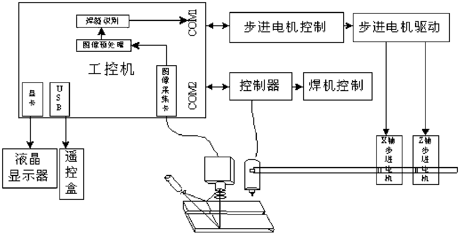
[0034] The welding seam tracking system based on laser vision is attached figure 1 As shown, it mainly includes an industrial computer, an X-axis motor, a Z-axis motor, a welding cabinet, a camera, and a laser diode. The COM1 port of the industrial computer is connected to the motor control and drive circuit, and is connected to the X-axis through the motor control and drive circuit. Motor, Z-axis motor, and then control the operation of X-axis motor and Z-axis motor. The output terminals of X-axis motor and Z-axis motor are connected to the welding cabinet, and the welding cabinet is driven by the X-axis motor and Z-axis motor. The controller and the welding machine control circuit, and the controller and the welding machine control circuit are connected to the COM2 port of the industrial computer, through which the industrial computer...


PUM

PropertyMeasurementUnit
frame rateaaaaaaaaaa

Abstract

The invention discloses a laser visual tracking system, which mainly comprises an industrial personal computer, wherein a COM 1 (Component Object Model) port of the industrial personal computer is connected with an X axis motor and a Z axis motor through a motor control and drive circuit; output ends of the X-axis motor and the Z-axis motor are connected with a welding torque; the controller of the welding torque and a welding machine control circuit are connected with the industrial personal computer; the industrial personal computer is also connected with a laser sensor for acquiring information on the welding torque and a workpiece in real time and delivering the acquired information to the industrial personal computer; the laser sensor is a visual sensing module and mainly comprises a camera and a laser diode; the camera is vertically aligned with the workpiece; a laser is slantwise arranged and forms an angle of 30 degrees with the laser; laser emitted by the laser irradiates the workpiece to form a narrow light strip; after the light strip is reflected or refracted by the workpiece, the light strip enters the camera to image, and the image is transferred to the industrial personal computer for processing; after the image is analyzed and processed by the industrial personal computer, an action command is emitted to the welding torque, the X-axis motor and the Z-axis motor.

Description

technical field [0001] The invention relates to the technical fields of detection and machine vision, in particular to a laser vision tracking system which is applied in the automatic tracking of welding seams in the welding process and is suitable for the automatic tracking of various types of welding seams at present. Background technique [0002] At present, many automation equipments on the market use arc tracking and teaching reproduction robots. The arc tracking structure is simple, convenient and flexible, but it is suitable for butt welds without grooves (submerged arc welding often does not open grooves). Difficult to achieve alignment tracking. The teaching and reproducing tracking method can guarantee the welding quality under the condition that the welding conditions are basically stable. However, due to the influence of various factors, the actual welding conditions often change, resulting in a decline in welding quality or even failure. The key to seam tracki...

Claims


Application Information

Patent Timeline
Patent Type & Authority Applications(China)
IPC IPC(8): B23K9/127
Inventor 李堂权李荣东陈晓莉
Owner CHENGDU XIONGGU JIASHI ELECTRICAL
Why Eureka
Try Eureka