Slurry filling pump with flow rate control function

A technology for filling pumps and thick slurry, which is applied in the direction of axial flow pumps, pumps, non-variable pumps, etc., which can solve the problems of wearing pipelines and filling drillings, etc., and achieves easy processing and manufacturing, convenient installation and use, and simple equipment structure Effect

Inactive Publication Date: 2013-07-17
济南友龙建筑安装有限公司
View PDF6 Cites 2 Cited by
  • Summary
  • Abstract
  • Description
  • Claims
  • Application Information

AI Technical Summary

Problems solved by technology

[0003] In order to solve the problem that the high-concentration filling slurry cannot be transported by traditional conveying equipment in the mining filling process and the problem that the low-concentration filling slurry cannot control the flow rate by gravity transportation and seriously wears the transportation pipeline and filling boreholes, the invention provides A dense slurry filling pump is developed. The thick slurry filling pump utilizes the characteristics of high viscosity and poor fluidity of the high-concentration filling slurry, and adopts the spiral impeller conveying method. It can push and drag the slurry to move together to complete the conveying process. This kind of thick slurry filling pump can not only smoothly transport all kinds of high-concentration filling slurry, but also can precisely control the filling slurry with the cooperation of frequency modulation motor. The flow rate and velocity of the body can be reduced, the wear of the conveying pipeline and the filling borehole can be reduced, energy saving can be achieved, and long-distance transportation at low pressure can be realized.

Method used


Image

  • Slurry filling pump with flow rate control function
  • Slurry filling pump with flow rate control function
  • Slurry filling pump with flow rate control function

Examples


Embodiment Construction

[0022] The present invention will be further described below in conjunction with the accompanying drawings and embodiments.

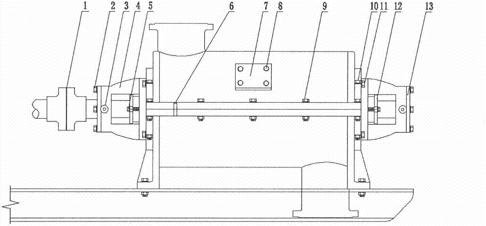
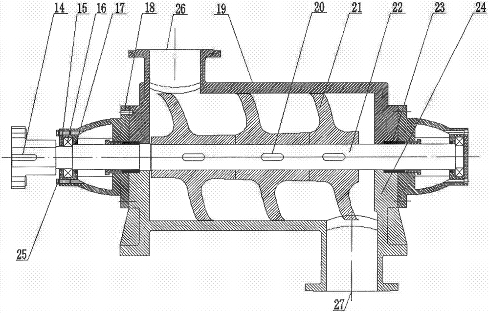
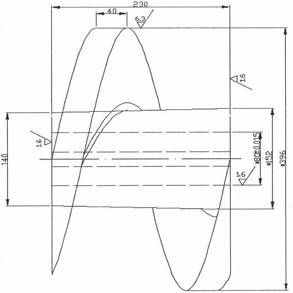
[0023] In the accompanying drawings, the main components of the thick slurry filling pump are the pump core and the pump casing. The pump core of this embodiment is composed of three helical impellers (21). The pump core composed of more than three or more helical impellers can transport the filling slurry with a longer distance and a higher pressure. It should be pointed out that no matter the pump core is composed of several helical impellers, the dimensions of each helical impeller are different. This is because the pitch of the pump core gradually changes from large to small, and the root diameter gradually changes from small to large, and its changing law is similar to a parabolic trajectory, which is a major factor in generating the delivery capacity. The pump core composed of three or more helical impellers (21) is assembled on the transmission ...


PUM


Abstract

Disclosed is a slurry filling pump with a flow rate control function. A main pump core is a spiral body with a varying pitch, a varying root diameter and an equal outer diameter and comprises three or a plurality of different spiral impellers (21) which are mounted on a transmission shaft (22) and are sleeved in a cylinder space (pump shell) formed by an upper pump body (19) and a lower pump body (24), a feed port (26) is arranged at one end of the upper pump body, a discharge port (27) is arranged at the other end of the lower pump body, the inner wall of the pump shell is closely matched with the periphery of the pump core to form a sealed wedge-shaped spiral space, and the wedge-shaped spiral space is naturally communicated with the feed port (26) and the discharge port (27). When the transmission shaft (22) is driven to continuously run forwards, the wedge-shaped spiral space can continuously reduce and generate positive pressure, media entering the spiral space are dragged, pushed and conveyed under the action of the pressure, the viscous force of the media and friction force, and the working principle is more suitable for conveying slurry with high concentration, viscosity and coarse aggregate content.

Description

technical field [0001] The invention relates to a filling slurry conveying device in the filling process in the mining field, in particular to a thick slurry filling pump capable of controlling the flow and velocity of the filling slurry. Background technique [0002] At present, it is known that in the process of mining filling, the transportation of filling slurry encounters two major problems, one is the flow rate and the other is the flow rate. The higher the concentration of the filling slurry is, the better the mining filling operation requires, but the filling slurry with a higher concentration cannot be transported normally. This is because the characteristics of filling slurry are that with the increase of slurry concentration, the viscous force increases, the fluidity becomes worse, the filling line decreases, and the difficulty of transportation increases. When the weight concentration of the filling slurry reaches more than 60%, the traditional sand pump, slurry...

Claims


Application Information

Patent Timeline
Patent Type & Authority Applications(China)
IPC IPC(8): F04D3/02
Inventor 邵志刚王晓明程兴民王兴民侯利民王传宗潘明友王勇徐秋鑫张传柱
Owner 济南友龙建筑安装有限公司
Why Eureka
Try Eureka