Fault detection apparatus of solenoid valve

A technology of fault detection and fault detection signal, applied in the direction of measuring device, measuring electricity, transportation and packaging, etc., can solve the problem of complex circuit composition, and achieve the effect of reducing the number of accessories

Inactive Publication Date: 2013-07-17
HYUNDAI MOBIS CO LTD
View PDF5 Cites 17 Cited by
  • Summary
  • Abstract
  • Description
  • Claims
  • Application Information

AI Technical Summary

Problems solved by technology

[0008] However, when the current is monitored using a shunt resistor in this way, an amplifier circuit is required due to the precision of the shunt resistor, and there is a problem that the circuit configuration becomes complicated.

Method used


Image

  • Fault detection apparatus of solenoid valve
  • Fault detection apparatus of solenoid valve
  • Fault detection apparatus of solenoid valve

Examples


Embodiment Construction

[0028] Hereinafter, referring to the drawings, the fault detection device for the solenoid valve according to the embodiment of the present invention will be described in detail. The thickness of the line and the size of the component elements shown in the drawings may be exaggerated for clarity and convenience of explanation. In addition, the following terms are terms defined in consideration of functions in the present invention, and may vary depending on the intention or convention of users, operators, etc. Therefore, the definition of these terms should be based on the comprehensive content in this specification.

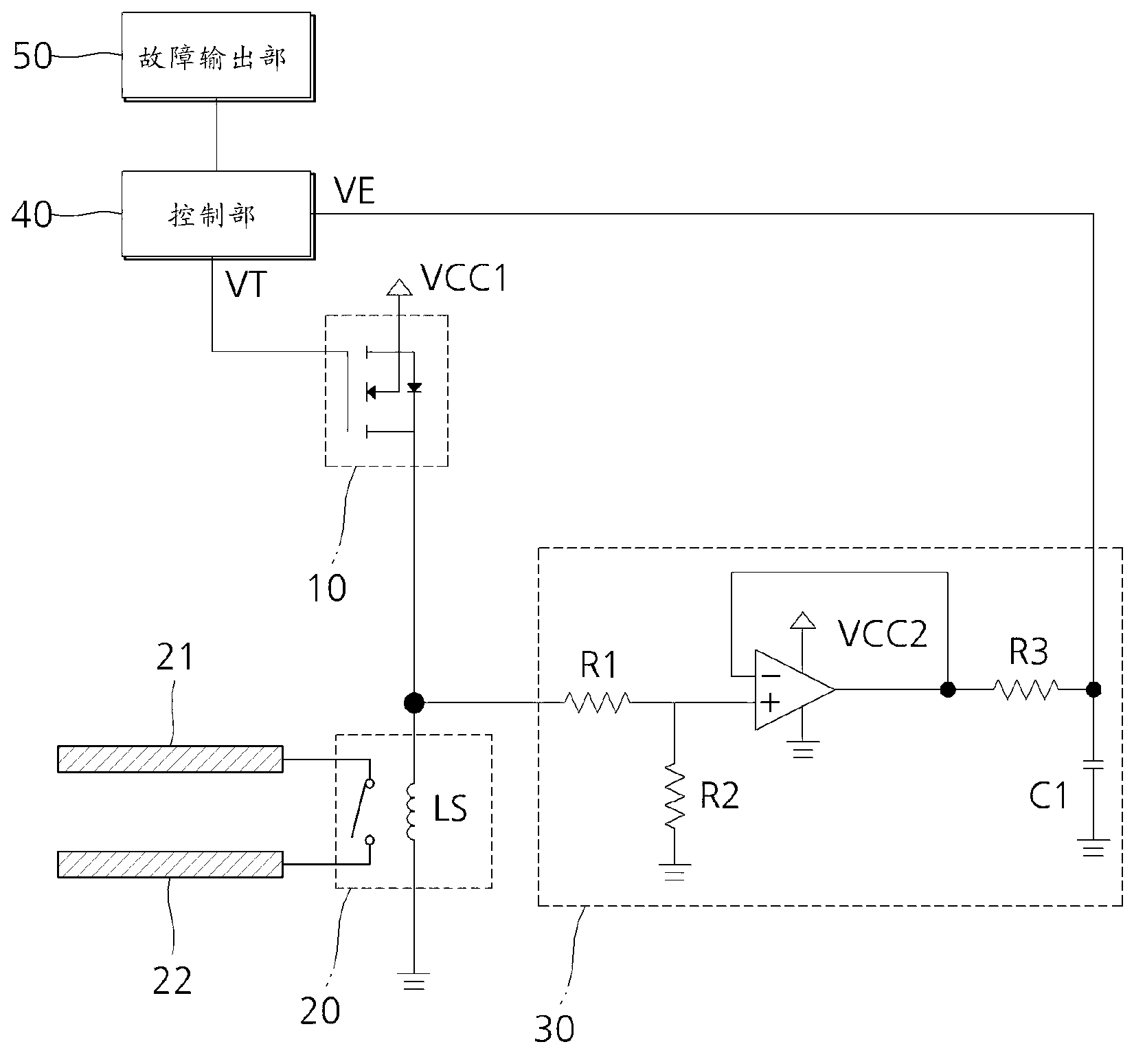
[0029] figure 1 It is a circuit diagram of a solenoid valve fault detection device according to an embodiment of the present invention.

[0030] Such as figure 1 As shown, a solenoid valve fault detection device according to an embodiment of the present invention includes a switch 10, a solenoid valve 20, a fault detection unit 30, a control unit 40, and a fault out...


PUM


Abstract

The invention provides a fault detection apparatus of a solenoid valve. The fault detection apparatus comprises a switch which switches to a power supply for an electromagnetic coil according to a fault detection signal which has specific energy smaller than a critical value of driving the solenoid valve, a fault detection portion which measures voltage across two ends of the electromagnetic coil and outputs detection voltage, a control portion which outputs the fault detection signal to the switch and based on the detection voltage input by the fault detection portion determines whether a fault of the solenoid valve occurs, and a fault output portion which outputs a fault state of the solenoid valve. According to the fault detection apparatus, the fault of the solenoid valve is detected by using a distribution voltage determined by resistance of the switch and intrinsic resistance of the electromagnetic coil, and thus a shunt resistor for monitoring current and a complicated amplifier circuit can be replaced, and the number of used accessories can be reduced.

Description

Technical field [0001] The present invention relates to a fault detection device for a solenoid valve, and in particular to a fault detection device for a solenoid valve that can use the inherent resistance of the solenoid coil to detect the fault of the solenoid valve during the non-operation of the solenoid valve. Background technique [0002] Generally speaking, a smart booster break system is an active control system that can assist control during regenerative braking of a hybrid vehicle by using a booster based on an electric motor. [0003] If the driver steps on the brake pedal, pressure is generated in the sub master cylinder, and the drive signal is connected to the solenoid valve, so that the Normal Close valve connected to the pedal simulator opens and connects to The Normal Open valve of the main master cylinder is closed. [0004] Therefore, the pressure generated in the auxiliary brake cylinder is transmitted to the pedal simulator through the opened solenoid valve, pu...

Claims


Application Information

Patent Timeline
Patent Type & Authority Applications(China)
IPC IPC(8): G01R31/00
CPCB60T8/363B60T13/686B60T17/221B60Y2400/3084B60Y2400/81
Inventor 金度君
Owner HYUNDAI MOBIS CO LTD
Why Eureka
Try Eureka