
Method for detecting solution leaching and groundwater pollution scope of acid in-situ leaching of uranium

A technology for groundwater pollution and in-situ leaching of uranium, which is used in measurement devices, water resources assessment, geophysical measurements, etc. Scope, time-consuming and other problems, to achieve the effect of quickly detecting the scope of acid in-situ leaching uranium leaching and groundwater pollution

Inactive Publication Date: 2013-07-17
BEIJING RESEARCH INSTITUTE OF CHEMICAL ENGINEERING AND METALLURGY +1
View PDF3 Cites 13 Cited by
  • Summary
  • Abstract
  • Description
  • Claims
  • Application Information

AI Technical Summary

Problems solved by technology

Due to the inhomogeneity of the formation and the uncertainty of hydrogeological parameters, the leaching range and the groundwater pollution range cannot be accurately determined in advance, so the location, depth and number of monitoring wells used to detect the leaching range and groundwater pollution range cannot be accurately determined
Sampling and analysis through monitoring wells not only requires the construction of enough monitoring wells and regular sampling and analysis, which is time-consuming, labor-intensive, costly, and professionally demanding, but also because the migrating groundwater partially contains components with high background, so that sometimes what is detected is not the real immersion fluid dispersion
At present, there is no effective method to detect the extent of uranium leaching and groundwater pollution in acid in-situ leaching

Method used


Image

  • Method for detecting solution leaching and groundwater pollution scope of acid in-situ leaching of uranium
  • Method for detecting solution leaching and groundwater pollution scope of acid in-situ leaching of uranium
  • Method for detecting solution leaching and groundwater pollution scope of acid in-situ leaching of uranium

Examples


Embodiment Construction

[0018] A method for detecting the scope of uranium leaching and groundwater pollution in acid in-situ leaching mining according to the present invention will be further described below in conjunction with the accompanying drawings and specific embodiments.

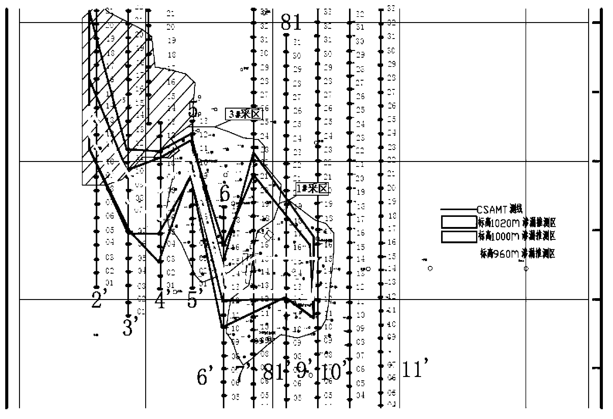
[0019] The present invention extracts uranium by acid method in situ leaching in Xinjiang Qisanqi Plant 1 # 、3 # The investigation of groundwater pollution in the stope has been applied, and the detection depth is about 1000m, that is, the elevation is above 200m.

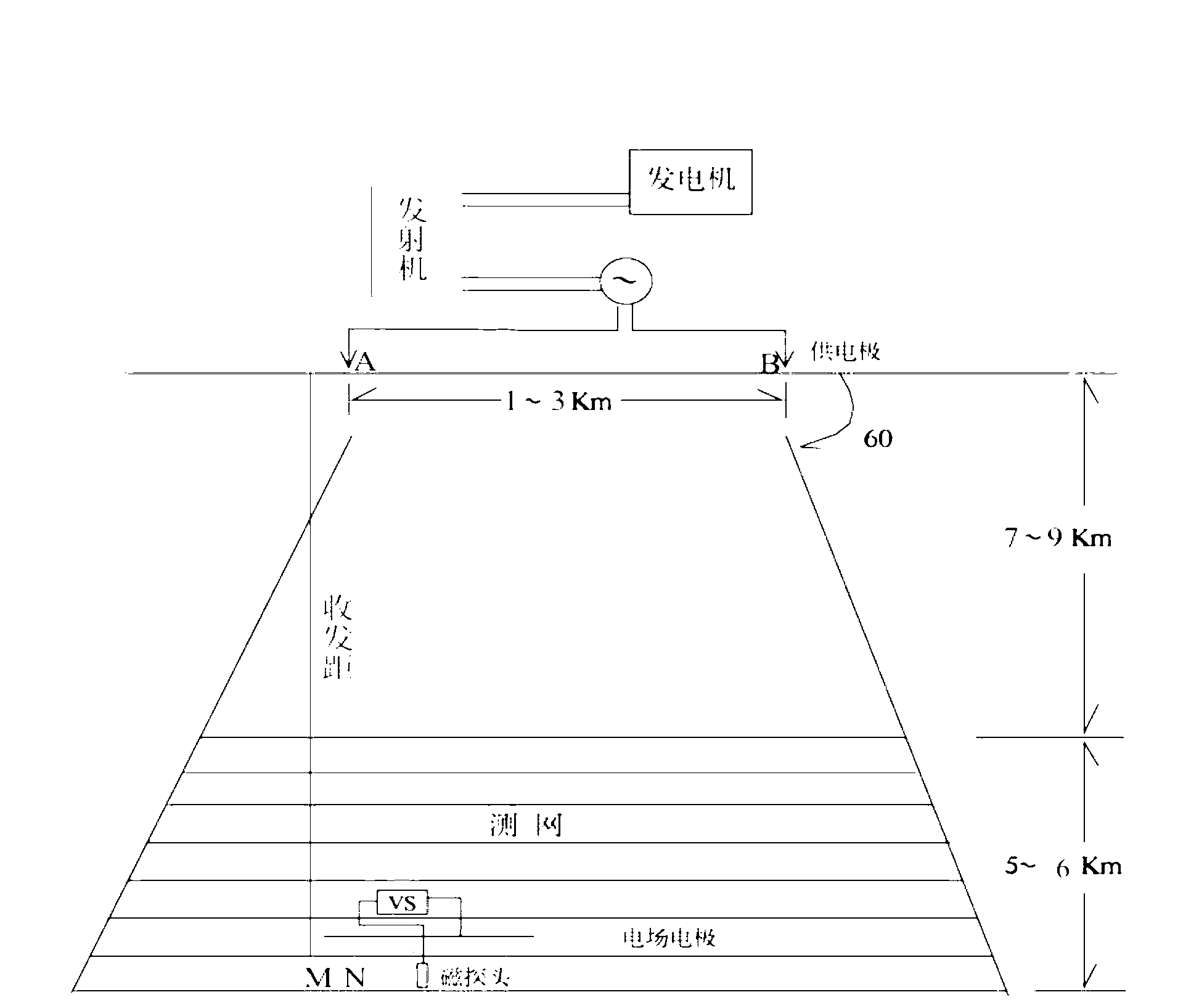
[0020] Such as figure 1 Shown, the method steps of adopting detection acid method in-situ leaching mining uranium leaching of the present invention and the scope of groundwater pollution are as follows:

[0021] (a) According to the site conditions, 10 parallel survey lines are laid out from west to east in the detection area, with a line distance of 50 meters. All positioning work (measuring points and launching points) are completed by GPS positioning, whic...


PUM


Abstract

The invention provides a method for detecting a solution leaching scope and a groundwater pollution scope of acid in-situ leaching of uranium. The method comprises the steps of: (a) distributing measuring lines in a detecting area and setting measuring points on the measuring lines; (b) transmitting signals of different frequencies through a transmitter, receiving signals of electric field and magnetic field which are coupled via the ground through a receiver, and converting the signals into collection data after the signals are subjected to calibration of scale values; (c) sequentially subjecting the collected date to curve smoothing, near field correction, one-dimensional inversion, two-dimensional inversion and electric property geological integrated interpretation to form a geophysical inversion result and a geological interpretation map of every measuring line; (d) subjecting the detecting area to three-dimensional geological modeling and subjecting the model to slicing display of different depths; and (e) combined with physical property data of the detecting target area, obtaining the solution leaching scope and the groundwater pollution scope of the acid in-situ leaching of uranium and the points where leakage occurs. The method for detecting the solution leaching scope and the groundwater pollution scope of the acid in-situ leaching of uranium is quick, economical, effective and simple to operate, and does not need constructing monitoring well and sampling analysis.

Description

technical field [0001] The invention belongs to the field of detection of uranium by in-situ leaching and groundwater pollution, in particular a method for detecting the leaching range of uranium in-situ leaching and the pollution range of groundwater by a controlled source audio frequency magnetotelluric sounding (CSAMT). Background technique [0002] The traditional detection of uranium leaching range and groundwater pollution range in in-situ leaching mining is through sampling and analysis of monitoring wells. Due to the inhomogeneity of the formation and the uncertainty of the hydrogeological parameters, the leaching range and groundwater pollution range cannot be accurately determined in advance, so the location, depth and number of monitoring wells used to detect the leaching range and groundwater pollution range cannot be accurately determined. Sampling and analysis through monitoring wells not only requires the construction of enough monitoring wells and regular sam...

Claims


Application Information

Patent Timeline
IPC IPC(8): G01V3/08
CPCY02A90/30
Inventor 徐乐昌胡祥云
Owner BEIJING RESEARCH INSTITUTE OF CHEMICAL ENGINEERING AND METALLURGY
Learn More