
A method for improving opening quality of an electroformed plate

An electroforming board and quality technology, applied in the manufacturing of circuits, electrical components, semiconductor/solid state devices, etc. problems such as opening size accuracy, to avoid the problem of infiltration and plating, simple and easy production management, and good opening shape

Inactive Publication Date: 2013-07-17
KUN SHAN POWER STENCIL
View PDF3 Cites 0 Cited by
  • Summary
  • Abstract
  • Description
  • Claims
  • Application Information

AI Technical Summary

Problems solved by technology

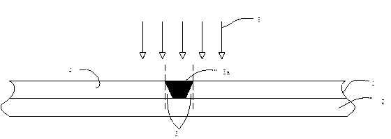
The direction of the exposure laser is vertically downward, and the laser has energy. Due to the thickness of the dry film, the laser energy on the surface of the dry film is the highest and the curing is the most complete. As the laser penetrates the dry film and penetrates below the surface of the dry film, the energy becomes more and more Low, the laser energy received by the dry film below the surface is insufficient, so that part of the dry film is incompletely cured, forming an uncured complete area 5, and the exposure opening has an inverted cone angle. In this way, in the subsequent development process, unexposed and uncured The complete dry film will be washed off by the developer, resulting in a large deviation in the opening size between the PCB surface and the printing surface, affecting the accuracy of the inverted opening size
During the electroforming process, such as figure 2 , image 3 As shown, the deposited material grows along the edge of the dry film of the exposure opening, and the formed shape completely clones the opening pattern after exposure and development, so the opening formed by electroforming also has a reverse taper angle of 14, which is the opening size of the printing surface 13 of the electroforming mask Too small, the deviation of the opening size between the PCB surface and the printing surface is large, which affects the accuracy of the opening size

Method used


Image

  • A method for improving opening quality of an electroformed plate
  • A method for improving opening quality of an electroformed plate
  • A method for improving opening quality of an electroformed plate

Examples


Embodiment Construction

[0048] In order to make the object, technical solution and advantages of the present invention clearer, the present invention will be further described in detail below in conjunction with the accompanying drawings and embodiments. It should be understood that the specific embodiments described here are only used to explain the present invention, not to limit the present invention.

[0049] refer to Figure 1-2 As shown, the method for improving the opening quality of electroformed plate of the present invention comprises the steps:

[0050] S10: After sticking the film on the mandrel, perform exposure, and expose the required opening pattern area on the dry film;

[0051] S11: Put the exposed dry film into the oven, set the baking temperature and baking time according to the needs, and bake the dry film;

[0052] S12: After the baking is completed, a development process is performed to remove the unexposed dry film by development.

[0053] Wherein, before said step S11, als...


PUM


Abstract

The invention discloses a method for improving opening quality of an electroformed plate, and the method comprises the following steps: S10: after mounting film on a core mold, performing exposure to well expose the needed opening pattern area on dry film; S11: placing the well-exposed dry film in a toaster, setting a roasting temperature and a roasting time according to needs, and performing dry film roasting; and S12: after complete roasting, performing a process of developing to remove the unexposed dry film. According to the method for improving opening quality of the electroformed plate of the invention, thick dry film is subjected to roasting after the exposure, which enables the dry film fully cured, thereby preventing the problem of diffusion coating; at the same time opening shapes are good, thereby lowering the deviation of opening sizes of a PCB surface size and a printing surface, and improving the opening quality; and roasting after the exposure allows the range of development dots further widened, providing a wider controlling range for the production to make the production control simpler and easier.

Description

[0001] technical field [0002] The invention belongs to the technical field of post-exposure baking of thick dry films, and in particular relates to a method for improving the opening quality of an electroformed plate. [0003] Background technique [0004] At present, in the field of PCB mask manufacturing, the photolithography process is generally used. First, the photoresist is coated on the substrate, then the pre-baking process is performed, and then the exposure process is performed, and finally the development process is performed. However, this process of coating photoresist has certain defects, such as photoresist residue and bridging phenomenon, thereby affecting the pattern quality. Moreover, if film is used in the photolithography process, the position accuracy of the exposed pattern is not high. If a chrome plate is used, each pattern area must correspond to a chrome plate, and the cost is too high. [0005] In order to solve the above problems, a direct e...

Claims


Application Information

Patent Timeline
IPC IPC(8): G03F7/26G03F7/40
Inventor 魏志凌高小平赵录军陈龙英
Owner KUN SHAN POWER STENCIL
Learn More