Compact, low flow resistance aerosol generator and method of operating the same

An aerosol and gas technology, which is applied in the direction of medical devices, nebulizers for treatment, inhalers, etc., can solve the problem of increasing the pressure head

Active Publication Date: 2013-07-17
多诺万 B. 耶茨
View PDF10 Cites 12 Cited by
  • Summary
  • Abstract
  • Description
  • Claims
  • Application Information

AI Technical Summary

Problems solved by technology

This potentially increases the pressure head required to accelerate the aerosol through these gaps

Method used


Image

  • Compact, low flow resistance aerosol generator and method of operating the same
  • Compact, low flow resistance aerosol generator and method of operating the same
  • Compact, low flow resistance aerosol generator and method of operating the same

Examples


Embodiment Construction

[0037] According to a preferred embodiment of the invention, liquid is evaporated from the second aerosol to produce a third aerosol comprising dry powder, gas and vapour. However, the aerosol may contain some residual liquid aerosol in addition to these dry particles.

[0038] According to another preferred embodiment of the invention, the evaporation of the liquid is carried out by applying infrared radiation. However, it is also possible to dry the aerosol by applying other forms of heat transfer, eg convection, or a combination of radiation and convection.

[0039] According to another preferred embodiment of the present invention, the preheating of the first volume flow of pressurized gas comprises directing the first volume flow through between the cylindrical inner wall of a tube and the cylindrical outer wall of a wedge-shaped elongated infrared bulb of a gap. This has proven to be very effective for the combination of efficient heat transfer and low flow resistance,...


PUM


Abstract

A method and an apparatus are described for generating a concentrated aerosol. A first heated volume flow of pressurized gas, a second volume flow of pre not heated dilution gas, and a third volume flow of fluid are provided. After creating a droplet aerosol from a solution, the aerosol solvent is quickly evaporated for creating a powder aerosol that then concentrated with a virtual impactor. The apparatus comprises a low flow resistance and achieves a high evaporation rate. The apparatus comprises a flow conditioner, nozzle, nozzle holder, and a concentrator.

Description

[0001] Cross References to Related Applications [0002] This application is a continuation-in-part claiming priority to US Nonprovisional Patent Application 11 / 315,951 filed December 22, 2005 and published June 28, 2007 as Publication No. US-2007-0144514-A1. This prior nonprovisional patent application 11 / 315,951 is hereby incorporated by reference in its entirety. [0003] governmental support [0004] This invention was made with Government support under Grant No. HL78281 from the National Institutes of Health, National Heart, Lung, and Blood Research Center. The US Government has certain rights in this invention. Background technique [0005] The present disclosure relates to a compact portable device for producing concentrated respirable dry particles from an aqueous solution or suspension. [0006] There is a growing need for the aerosol delivery of large masses of biological and other agents to the respiratory tract. Many devices that generate liquid aerosols may no...

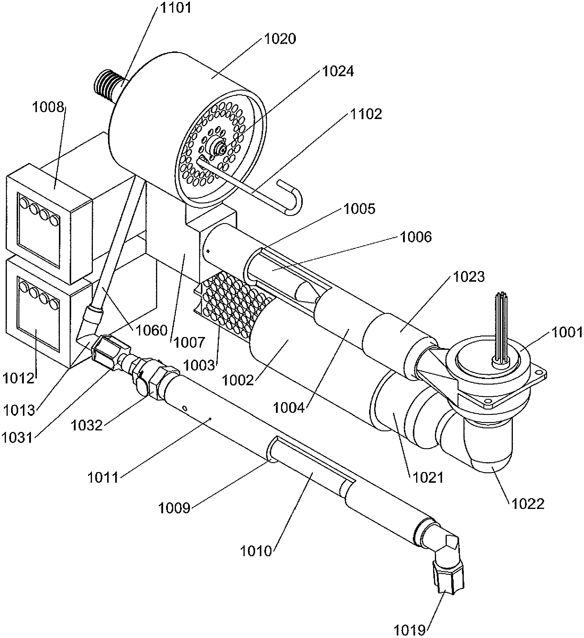
Claims


Application Information

Patent Timeline
Patent Type & Authority Applications(China)
IPC IPC(8): A61M11/02A61M15/02B05B1/06
CPCA61M2011/003A61M2016/0039B05B12/00A61M2205/3653A61M2205/3372A61M2016/0015A61M2206/14A61M2202/064A61M16/0066A61M15/0086A61M2205/368A61M2202/062A61M11/06A61M11/003A61M11/042
Inventor 多诺万·B.·耶茨
Owner 多诺万 B. 耶茨
Why Eureka
Try Eureka