Luminescent material and light emitting device comprising such luminescent material

A technology of luminescent materials and light-emitting devices, which is applied in the direction of luminescent materials, semiconductor devices, gas discharge lamp parts, etc., can solve the problems of low chemical stability and achieve the effect of improving efficiency

Inactive Publication Date: 2013-07-17
KONINK PHILIPS ELECTRONICS NV
View PDF11 Cites 6 Cited by
  • Summary
  • Abstract
  • Description
  • Claims
  • Application Information

AI Technical Summary

Problems solved by technology

[0009] low chemical stability,

Method used


Image

  • Luminescent material and light emitting device comprising such luminescent material
  • Luminescent material and light emitting device comprising such luminescent material
  • Luminescent material and light emitting device comprising such luminescent material

Examples


Embodiment Construction

[0040] The detailed description of the embodiments given below will mainly focus on examples of light emitting materials. As for the light emitting device, system and method proposed in the present invention, useful descriptions have been given in the prior art and existing related papers or products can be referred to.

[0041] Example I

[0042] Example I refers to Ca 5 (PO 4 ) 3 F:Pr 3+ (l%)Na + (1%), which can be made in the following manner.

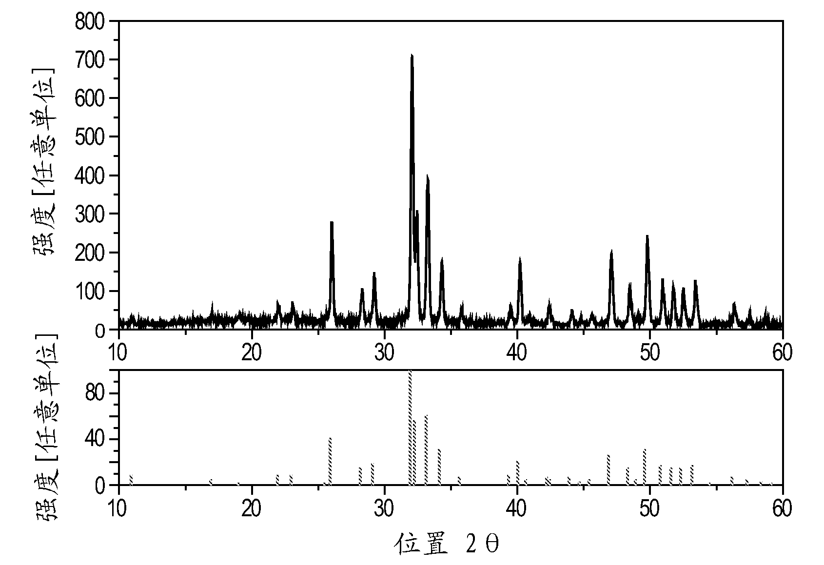
[0043] Starting material 1.009 g CaCO 3 , 4.0004 g CaHPO4 .2H 2 O, 0.32 g of nanoscale CaF 2 and 0.076 g of PrF 3 and 0.016 g of NaF were ground for 0.5 h. The mixture was then annealed at about 1100°C for 1 hour under nitrogen. Finally, the material was ground and sieved through a 36 μm sieve.

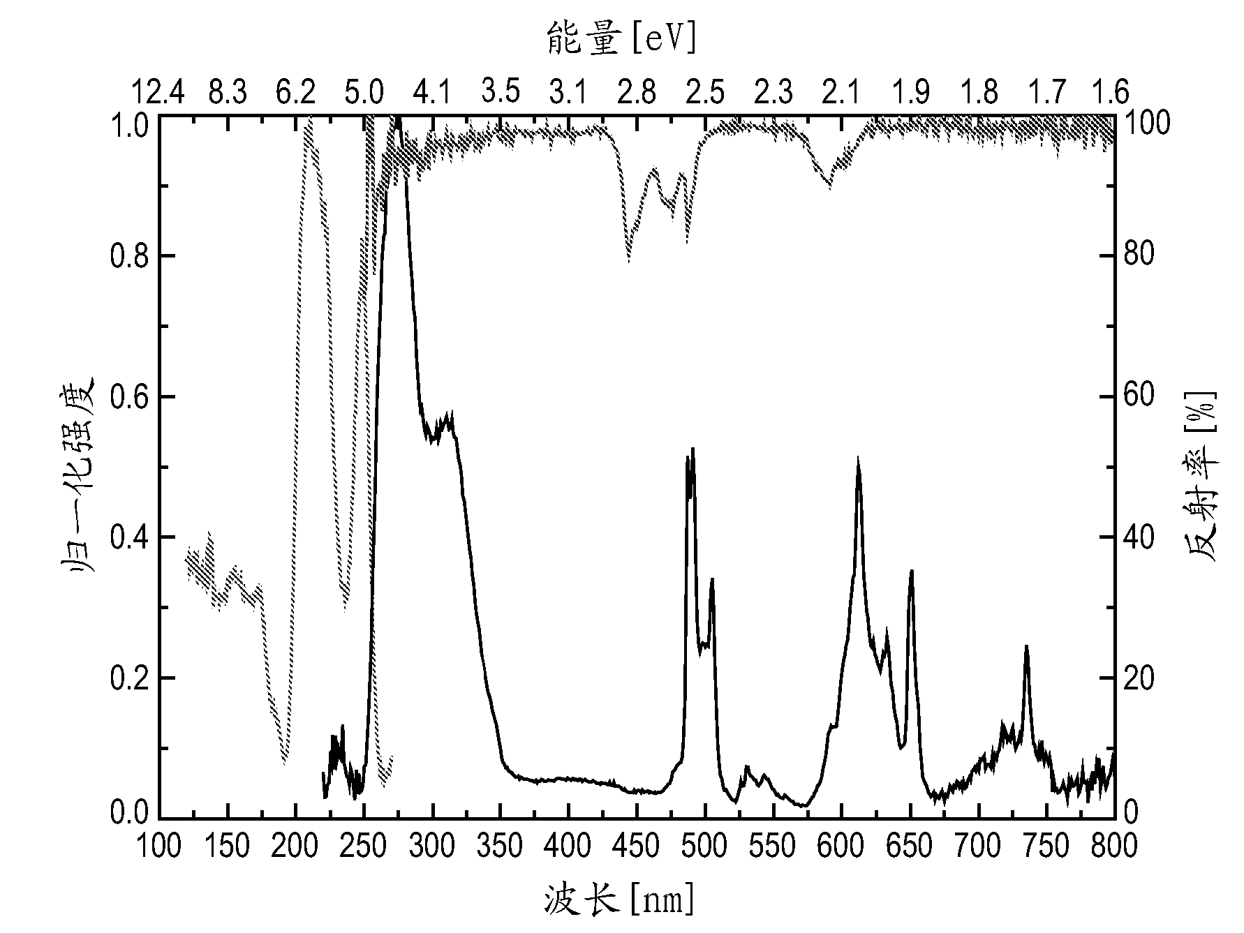
[0044] Figure 1 shows the XRD pattern of the material of Example I. Figure 2 shows the excitation spectrum (left spectrum), emission spectrum (right spectrum) and reflection spectrum (upper right spectrum) of the material of Ex...


PUM


Abstract

The invention provides a luminescent material comprising a component selected from the group comprising (Y1-xLux)9LiSi6O26:Ln or / and AE5(PO4)3F:Ln,A, wherein Ln is a trivalent rare earth metal, AE is a divalent alkaline earth metal, and A is a monovalent alkaline metal, x > 0.0 and < 1.0. The luminescent material has an emission peak in the UV-C range when being excited by light in the UV spectrum range. The invention further provides a light emitting device comprising the said luminescent material and a method of using said light emitting device for disinfection or purification of air, water or surfaces.

Description

technical field [0001] The present invention relates to the field of luminescent materials, in particular to luminescent materials for use in light emitting devices emitting UV radiation. Background technique [0002] UV radiation sources have found many fields of application, such as spectroscopy, cosmetic skin care, medical skin care, disinfection or purification of water and air, polymer hardening, photochemistry, surface curing, and wafer processing. [0003] Many of the above application fields require deep UV radiation, ie UV-C (200-280nm) or even VUV radiation (100-200nm), where fast switching cycles and invariance to temperature changes are desirable features. [0004] Low pressure Hg discharge lamps are currently widely used as sources of UV radiation and they have an emission spectrum dominated by two lines (ie at 185 and 254 nm). However, increasing the Hg vapor pressure results in a nearly continuous spectrum extending from the deep UV to the deep red spectral r...

Claims


Application Information

Patent Timeline
Patent Type & Authority Applications(China)
IPC IPC(8): C09K11/73C09K11/79H01J61/44F21Y101/00
CPCH01J61/44A61L2/10H01J61/35C09K11/7711H01L33/502C09K11/7706C09K11/7774C09K11/55F21S13/00F21Y2101/00C09K11/7758
Inventor G.格雷伊尔T.杰斯特H.贝坦特鲁普J.普勒瓦
Owner KONINK PHILIPS ELECTRONICS NV
Why Eureka
Try Eureka