
washing machine

A washing machine and outer cylinder technology, applied in the field of household appliances, can solve the problems of reducing the reliability of safety switches, poor parts versatility, and not meeting environmental protection requirements, etc., and achieve the effects of small wear, extended life, and high reliability

Inactive Publication Date: 2017-07-18
WUXI LITTLE SWAN CO LTD
View PDF6 Cites 0 Cited by
  • Summary
  • Abstract
  • Description
  • Claims
  • Application Information

AI Technical Summary

Problems solved by technology

The wear, deformation or even breakage of the mechanical pendulum of the existing safety switch, the deformation of the reed of the electrical switch, and the failure of the micro switch will greatly reduce the reliability of the safety switch; washing machines with different capacities require different In order to achieve the best effect, the safety switch is matched with the safety switch, and the commonality of the parts is not good; in addition, before the eccentric dehydration bucket stops running, the noise generated by the impact does not meet people's increasing environmental protection needs

Method used


Image

  • washing machine
  • washing machine
  • washing machine

Examples


Embodiment 1

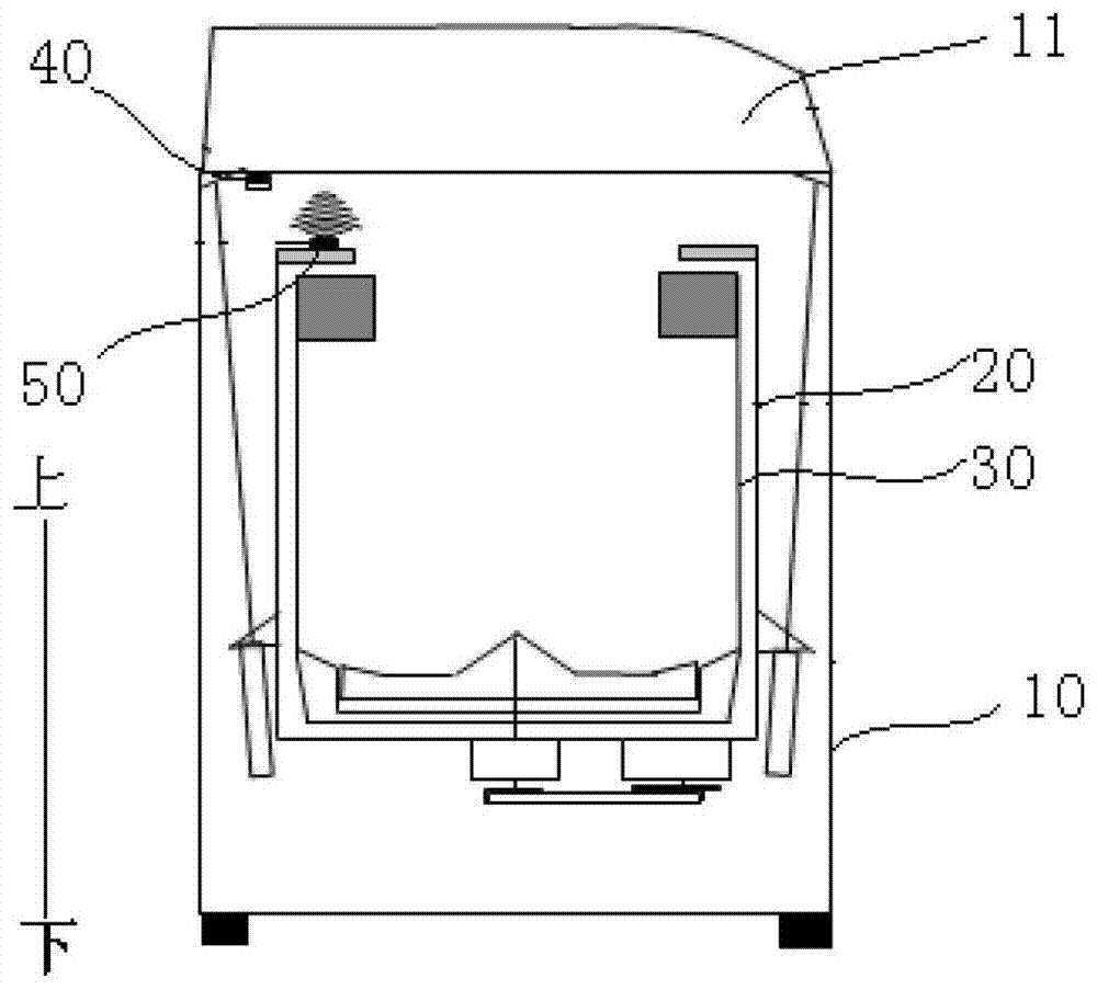
[0039] Such as figure 1As shown, the top of the outer cylinder 20 is open, the magnetoresistive sensor 50 is arranged on the upper part of the outer cylinder 20 and the magnetic field induction part 52 is arranged upward, and the magnetic part 40 is arranged under the workbench 11 and the magnetic surface of the magnetic part 40 is arranged downward.

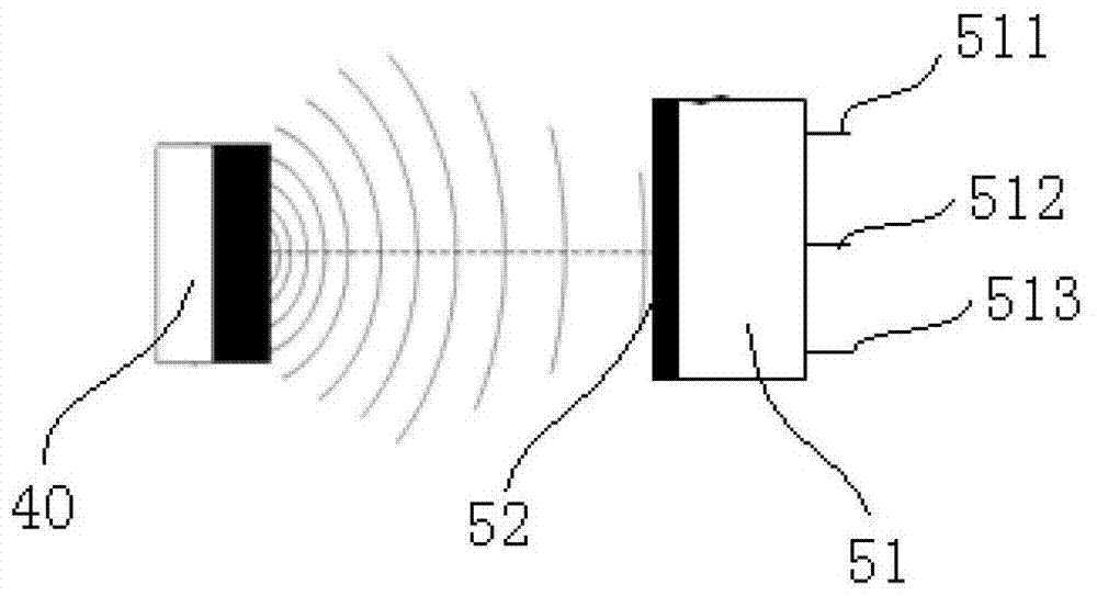
[0040] Specifically, the reluctance sensor 50 is installed on the upper plane of the outer cylinder 20, the outer cylinder 20 is connected to the housing 10 through a suspension spring, and the rotation of the inner cylinder 30 during the dehydration process will drive the outer cylinder 20 to shake. The magnetic surface of the magnetic element 40 faces the magnetic field sensing portion 52 , and the magnetic element 40 is located outside the magnetoresistive sensor 50 in the radial direction of the outer cylinder 20 .

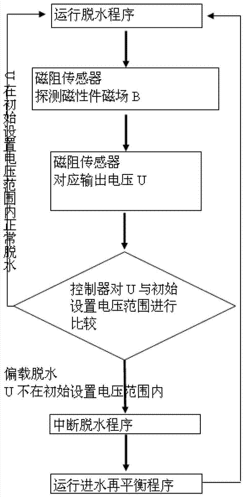
[0041] Combine below image 3 The dehydration process of the washing machine according to Embodiment 1 of th...

Embodiment 2

[0045] Such as Figure 4 As shown, the top of the outer cylinder 20 is open, the magnetic part 40a is arranged on the upper part of the outer cylinder 20 and the magnetic surface of the magnetic part 40a is arranged upward, and the magnetoresistive sensor 50a is arranged under the workbench 11 and the magnetic field induction part is arranged downward.

[0046] Specifically, the magnetic member 40a is installed on the upper surface of the outer cylinder 20, the outer cylinder 20 is connected to the housing 10 through a suspension spring, and the rotation of the inner cylinder 30 during the dehydration process will drive the outer cylinder 20 to shake. The magnetic surface of the magnetic element 40 a faces the magnetic field induction part, and the magnetoresistive sensor 50 a is located outside the magnetic element 40 a in the radial direction of the outer cylinder 20 .

[0047] The dehydration process of the washing machine according to Embodiment 2 of the present invention ...


PUM


Abstract

The invention discloses a washing machine, comprising: a casing; a controller; an outer cylinder, the outer cylinder is installed in the casing; an inner cylinder, the inner cylinder is pivotally installed in the outer cylinder; a magnetic part, the magnetic part is arranged on one of the outer cylinder or the housing; and a magnetoresistive sensor, the magnetoresistance sensor is arranged on the other of the outer cylinder or the housing, and The magnetic parts are oppositely arranged to sense the magnetic parts, and the magnetoresistive sensor is connected with the controller. According to the washing machine of the embodiment of the present invention, the non-contact detection method is used to detect whether the dehydration of the washing machine is balanced, which has little wear on the washing machine, prolongs the life of the washing machine, and has high reliability; the magnetoresistive sensor and the magnetic parts have strong versatility, and the hardware does not change , For different dehydration systems, it is only necessary to adjust the controller program to compare the threshold voltage to achieve matching; and the washing machine is non-contact detection, and no collision will occur during the detection process, so there will be no noise.

Description

technical field [0001] The invention relates to the technical field of home appliance preparation, and more specifically, to a washing machine. Background technique [0002] During the dehydration process of the washing machine, if the clothes are not evenly distributed, the dehydration bucket will run eccentrically, causing the suspended water bucket to move abnormally and hit the cabinet, posing a greater threat to the machine and personal safety. At present, the unbalance detection of dehydration is mainly through the bucket hitting the safety switch swing lever. After the computer board detects a specific voltage signal change, the dehydration is stopped and the water intake rebalance program is automatically run to make the laundry evenly distributed, and then continue dehydration. The wear, deformation or even breakage of the mechanical pendulum of the existing safety switch, the deformation of the reed of the electrical switch, and the failure of the micro switch will...

Claims


Application Information

Patent Timeline
Patent Type & Authority Patents(China)
IPC IPC(8): D06F37/20
Inventor 康菲黄升野
Owner WUXI LITTLE SWAN CO LTD
Learn More