Air door bridge and top camshaft engine

A valve bridge and valve technology, which is applied in the direction of engine components, machines/engines, valve devices, etc., can solve problems such as aggravating the unbalanced force of the valve, and achieve the effect of small width, avoiding insufficient strength, and reducing height

Active Publication Date: 2013-07-24
ANHUI JIANGHUAI AUTOMOBILE GRP CORP LTD
View PDF11 Cites 2 Cited by
  • Summary
  • Abstract
  • Description
  • Claims
  • Application Information

AI Technical Summary

Problems solved by technology

However, on the one hand, the existence of the boss makes the end of the valve rocker arm and the valve bridge lift up too high, whic

Method used


Image

  • Air door bridge and top camshaft engine
  • Air door bridge and top camshaft engine
  • Air door bridge and top camshaft engine

Examples


Embodiment Construction

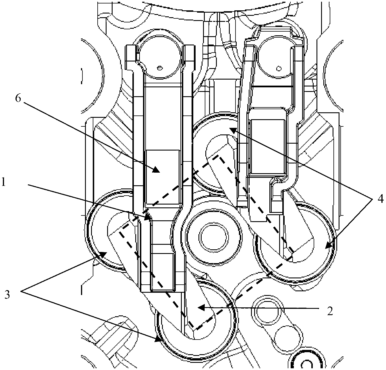
[0026] combine figure 1 and Figure 6 , the camshaft (not shown) of the overhead camshaft engine is located on the top surface of the cylinder head, and the cam of the camshaft is pressed on the rocker arm roller 6, so that the camshaft drives the valve rocker arm 1 to swing by rotation, and the valve rocker arm 1 Press down the valve bridge 2, the valve bridge 2 then presses down the intake valve 3 or the exhaust valve 4, and the intake valve 3 or the exhaust valve 4 is reset by the valve spring 5. In engine design, an important starting point is to realize the miniaturization and compact layout of the engine as much as possible, so the connection between the two intake valves 3 and the two exhaust valves 4 of the overhead camshaft engine forms a rhombus Arrangement (such as figure 1 shown by the dotted line).

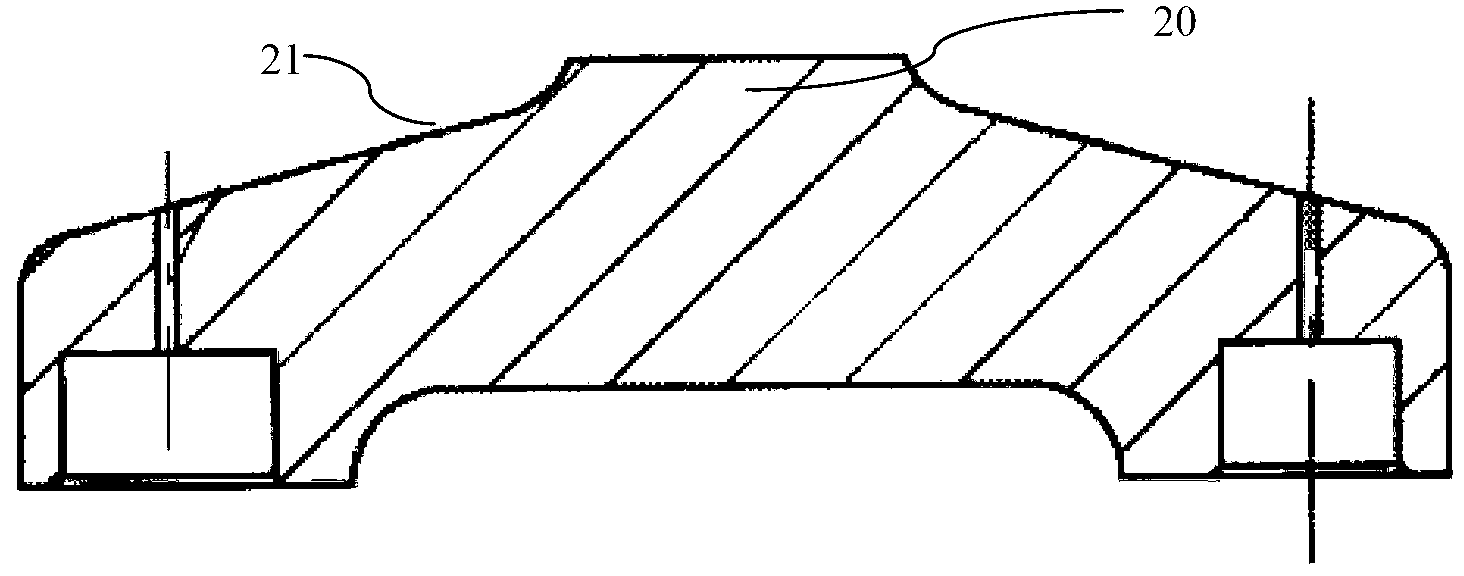
[0027] refer to figure 2 , in the prior art, the valve bridge 2 continues to extend upwards on the top surface 21 with a boss 20 , and the boss 20 is slidably ma...


PUM


Abstract

The invention provides an air door bridge. The two ends of the air door bridge are provided with mechanisms matched with two air doors; the top surfaces of the air door bridge are provided with grooves which are matched with air door rocker arms; and symmetric axes of the grooves intersect with each other relative to a connecting line between the mechanisms, but are not vertical to each other. The invention further provides a top camshaft engine adopting the air door bridge. Due to the adoption of the air door bridge, the height of the engine can be further reduced, and miniaturization of the engine is realized.

Description

technical field [0001] The invention relates to the field of engines, in particular to a valve bridge with oblique grooves. Background technique [0002] The engine valve bridge is an important part in the engine valve train. When the engine is running, the crankshaft drives the camshaft to rotate through the timing system, the camshaft drives the valve rocker arm, and the valve rocker arm transmits the phase to the two valves through the valve bridge, so that the valve can be effectively opened and closed during the high-speed operation of the engine , to achieve gas distribution function. [0003] For the cylinder with the camshaft overhead, in order to achieve a compact engine layout, the intake and exhaust valves are generally arranged in a diamond shape, which can reduce the width of the engine. It is inclined for the connecting line, such as application number: 96192117.X, application date: 1996-10-16, shown in the accompanying drawing of the Chinese invention patent...

Claims


Application Information

Patent Timeline
IPC IPC(8): F01L1/26
Inventor 马勇陆荣荣孟祥山
Owner ANHUI JIANGHUAI AUTOMOBILE GRP CORP LTD
Why Eureka
Try Eureka