Coated cogwheel

A coating and gear technology, applied in coating, belt/chain/gear, metal material coating process, etc., can solve the problems of limiting gear life, coating peeling, etc., and achieve the effect of avoiding peeling and good performance characteristics

Inactive Publication Date: 2013-07-24
SIEMENS AG
View PDF8 Cites 3 Cited by
  • Summary
  • Abstract
  • Description
  • Claims
  • Application Information

AI Technical Summary

Problems solved by technology

Of course, in the case of uneven loading of the coated gear, such coating spalling may occur, which greatly limits the life of the gear

Method used


Image

  • Coated cogwheel
  • Coated cogwheel
  • Coated cogwheel

Examples


Embodiment Construction

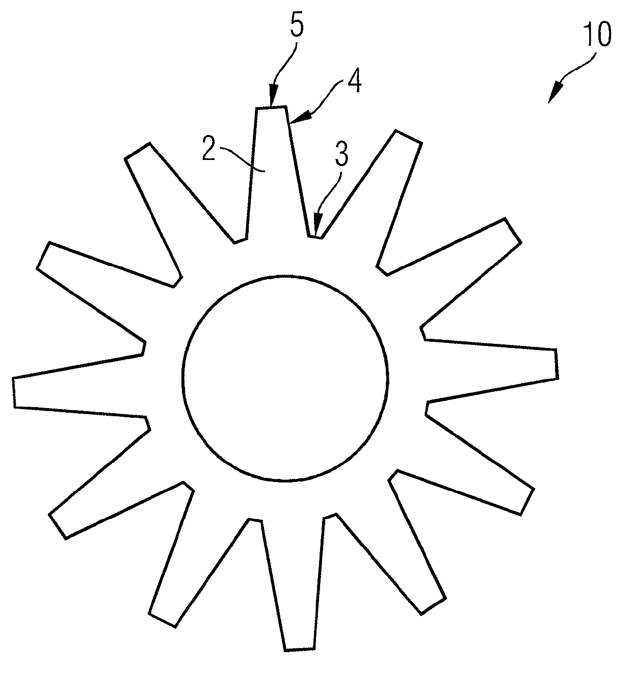
[0028] figure 1 A view is shown of a gear body 10 to be coated, which consists of a base material, for example hardened steel such as 16MnCr5 or 18CrNiMo7-6. Gear teeth 2 are arranged along the outer periphery of the gear body 10 , and the gear teeth respectively have a dedendum 3 , a tooth surface 4 and a tooth top 5 .

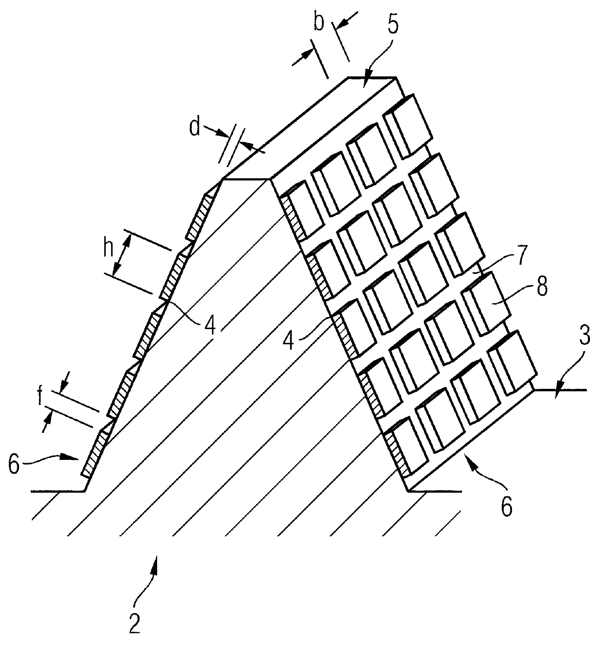
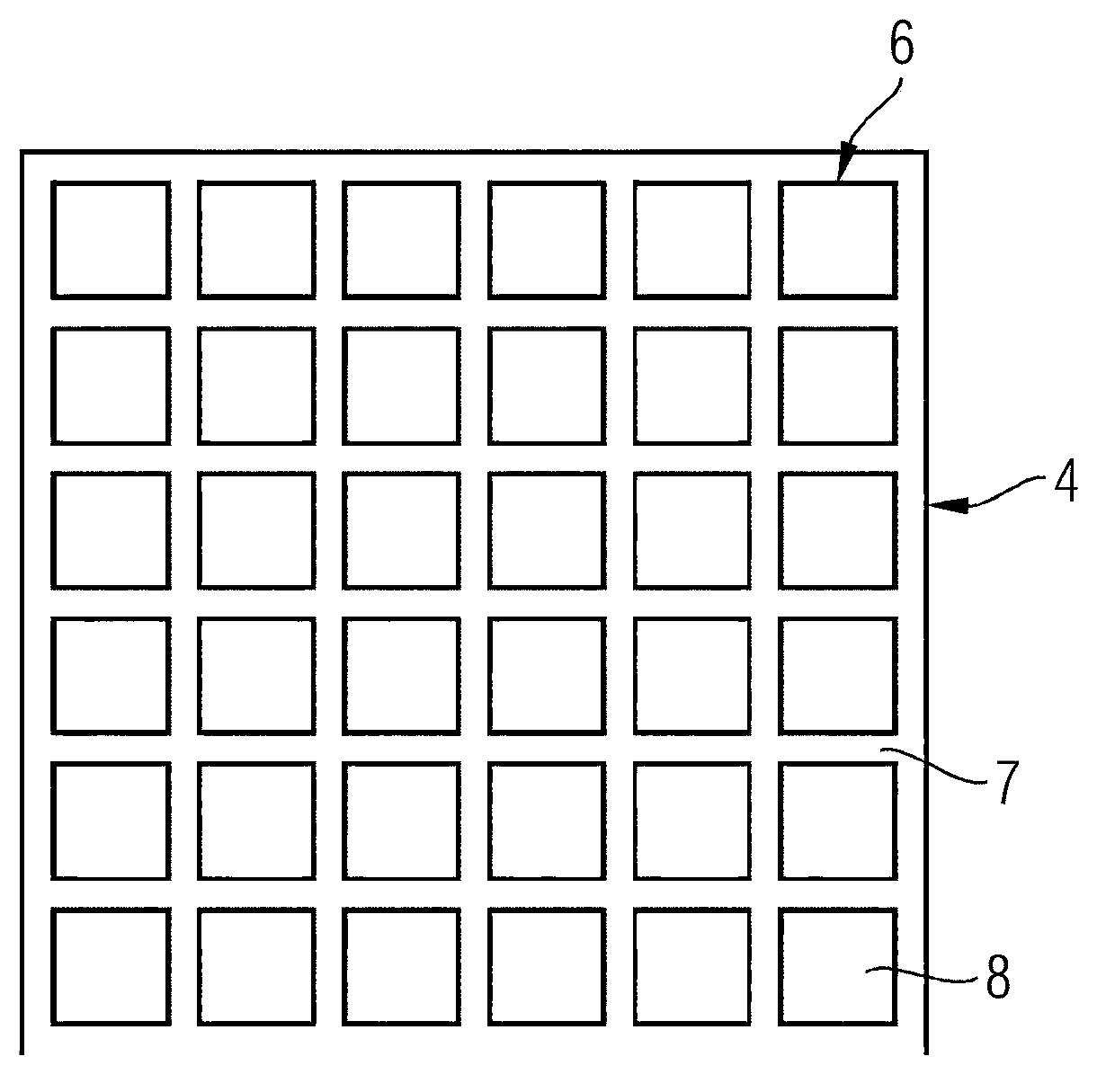
[0029] figure 2 shown in figure 1 A perspective view of the gear tooth 2 of the gear body 10 shown in . A coating 6 is arranged on both tooth flanks 4 of the gear tooth 2 , which coating is harder than the base material of the gear body 10 and thus reduces the wear of the tooth flanks 4 . The coating 6 of thickness d is not formed closed on the tooth flank 4 , but is divided into a plurality of sections 8 . Two adjacent sections 8 are separated from each other by a seam 7 with a seam width f. The segments 8 each have a width b and a height h. The dedendum 3 and the tooth tip 5 are free of coating 6 in order not to limit the elasticity in these regions....


PUM


Abstract

The cogwheel has a main portion which is made from basis material with lesser hardness. A layer (6) is arranged on portion of cogwheel main portion and provided with greater hardness. The layer is subdivided by seams (7) into multiplicity of segments (8) in spaced-apart relationship. The layer is arranged on tooth flank (4) of cogwheel main portion. The seams are sized to cut completely through layer and to extend into cogwheel main portion. An independent claim is included for a method for producing coated cogwheel.

Description

technical field [0001] The invention relates to a coated gear and a method for producing the coated gear. Background technique [0002] Surface hardening is a common method for hardening drive components and gears, which is described, for example, in DE569453A and DE2109494B. This results in high surface hardness and compressive stresses, which prevent wear and failure modes caused by Hertzian pressure. [0003] It is also known that special coatings of the pressure-loaded regions of gears can further reduce wear. DE19724661C2 describes a transmission component with a carbon mesh in a diamond-like structure and a ceramic TiN coating. Of course, under uneven loading of the coated gear, such coating spalling may occur, thereby greatly limiting the life of the gear. Contents of the invention [0004] The object of the present invention is to provide a coated gear wheel which does not have this disadvantage. [0005] This object is achieved by a coated gear comprising a ge...

Claims


Application Information

Patent Timeline
Patent Type & Authority Applications(China)
IPC IPC(8): F16H55/17F16H55/06B32B33/00
CPCC23C16/04F16H55/06F16H57/041B05D5/00Y10T74/1987
Inventor 让·安德烈·迈斯
Owner SIEMENS AG
Why Eureka
Try Eureka