
Point contact type optical fiber ultrasonic sensor

An ultrasonic and sensor technology, applied in the field of measurement, can solve the problems of the highest response frequency stay, difficult high-frequency ultrasonic spectrum range, high-frequency ultrasonic response characteristics are not ideal, etc., to achieve the effect of real-time monitoring

Inactive Publication Date: 2013-07-24
SHANGHAI UNIV
View PDF7 Cites 15 Cited by
  • Summary
  • Abstract
  • Description
  • Claims
  • Application Information

AI Technical Summary

Problems solved by technology

However, due to the limitation of the slender structure of the optical fiber, the fiber-optic ultrasonic sensor researched and developed at present, the response characteristics to high-frequency ultrasonic waves are not ideal.
At present, the highest response frequency of most ultrasonic sensors only stays between tens of kHz and hundreds of kHz, and it is difficult to cover the spectrum range of high-frequency ultrasonic waves generated by partial discharge.
On the other hand, at present, most types of fiber optic ultrasonic sensors are still of the surface contact type, so there are still certain requirements for the flatness of the contacted solid surface.
Often due to the unsatisfactory surface coupling state and frequent changes, the sensitivity of the sensor is greatly reduced, and many uncertain factors are brought to the measurement process

Method used


Image

  • Point contact type optical fiber ultrasonic sensor
  • Point contact type optical fiber ultrasonic sensor
  • Point contact type optical fiber ultrasonic sensor

Examples


Embodiment 1

[0046] see figure 1 And Fig. 2, this point-contact optical fiber ultrasonic sensor, comprises core part and package shell, is characterized in that: described core part is made of fiber optic ultrasonic sensitive element; Described package shell is electric insulating shell; Described optical fiber ultrasonic sensitive element is packaged Inside said electrically insulating housing, a single-piece sensor is constituted.

Embodiment 2

[0048] This embodiment is basically the same as Embodiment 1, and the special features are:

[0049] The optical fiber ultrasonic sensitive element consists of a single-mode optical fiber coated with a polyimide resin film on the surface, an optical fiber F-P resonant cavity formed by two spaced fiber gratings, and a ceramic plug glued together with the head of the single-mode optical fiber. Core composition.

[0050] The packaging structure in which the sensitive element of the optical fiber sensor is encapsulated in the electrical insulation shell applies effective stress to the optical fiber F-P resonant cavity in advance, so that the sensor has the function of sensing high-frequency ultrasonic waves.

[0051] The inner end surface of the ceramic ferrule is supported by a plastic spring, and the plastic spring is installed in the inner hole of the packaging shell in a compressed state, and applies effective stress to the optical fiber F-P resonant cavity in advance.

Embodiment 3

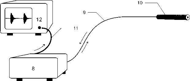
[0053] Taking the optical fiber ultrasonic measurement system related to the embodiment of the present invention as shown in FIG. 2A as an example, the measurement of the ultrasonic signal propagating in the surface layer of the metal plate by using the point contact optical fiber ultrasonic sensor of the present invention will be described.

[0054] For example, using figure 1 The optical fiber ultrasonic sensitive element shown in A, and the figure 1 The packaging structure of the sensor shown in B can constitute a point contact fiber optic ultrasonic sensor 10 .

[0055] For example, using figure 1 The fiber optic ultrasonic sensitive element shown in A, in which the center wavelength of the two fiber gratings 2a and 2b is 1552.3nm, the line width is 1.8nm, the reflectivity is 10%, and the fiber F-P resonant cavity length L The surface is coated with a single-layer polyimide resin film, and the ceramic ferrule is the fiber optic connector material, with an outer diameter ...


PUM

PropertyMeasurementUnit
wavelengthaaaaaaaaaa
widthaaaaaaaaaa
lengthaaaaaaaaaa

Abstract

The invention discloses a point contact type optical fiber ultrasonic sensor based on optical fiber grating technology. The sensor comprises a core part and an encapsulation outer shell. The core part is composed of an optical fiber ultrasonic sensitive element, the encapsulation outer shell is an electric insulation outer shell, and the optical fiber ultrasonic sensitive element is encapsulated in the electric insulation outer shell to form the individual unit sensor. The sensor has the advantages that sensor is small in size and has no metal parts, requirements for planeness of surfaces of measured points are not high, and point contact measurement can be achieved; and the sensor is especially suitable for detection for high frequency ultrasonic signals generated by partial discharge in high voltage equipment of high voltage transmission transformer, gas insulation switch cabinet (GIS) and the like, and is a novel optical fiber ultrasonic sensor.

Description

technical field [0001] The invention belongs to the field of measurement, and in particular relates to a point-contact optical fiber ultrasonic sensor for detecting high-frequency ultrasonic vibrations propagated on a solid surface. Background technique [0002] In the industrial field, traditional piezoelectric ceramic ultrasonic sensors based on the piezoelectric effect have been used for a long time to measure ultrasonic signals transmitted in solid objects such as metals or on their surfaces. However, the piezoelectric ceramic ultrasonic sensor has high requirements on the flatness of the contact part of the solid surface, and it cannot be used directly for some irregular surfaces, such as curved surfaces. On the other hand, in order to obtain high detection sensitivity, it is necessary to maintain good contact between the sensor surface and the solid surface. When in use, it is often necessary to apply an acoustic wave coupling medium between the two contact surfaces, ...

Claims


Application Information

Patent Timeline
Patent Type & Authority Applications(China)
IPC IPC(8): G01R31/12G01N29/04
Inventor 王陆唐方捻黄肇明
Owner SHANGHAI UNIV
Learn More