Vehicle collision risk prediction apparatus

A predictive device, a dangerous technology, applied in the direction of measuring devices, vehicle components, vehicle safety arrangements, etc., can solve problems that cannot reduce accidents, and achieve the effect of preventing collision accidents

Inactive Publication Date: 2013-07-31
HITACHT MAXELL LTD
View PDF8 Cites 20 Cited by
  • Summary
  • Abstract
  • Description
  • Claims
  • Application Information

AI Technical Summary

Problems solved by technology

[0005] Patent Document 1, as described above, describes "a method of detecting obstacles on roads using a millimeter-wave sensor installed on the roadside, which is based on measurement data obtained by scanning the millimeter-wave sensor and an ...

Method used


Image

  • Vehicle collision risk prediction apparatus
  • Vehicle collision risk prediction apparatus
  • Vehicle collision risk prediction apparatus

Examples


Embodiment 1

[0160] Hereinafter, Example 1 of the present invention will be described in detail.

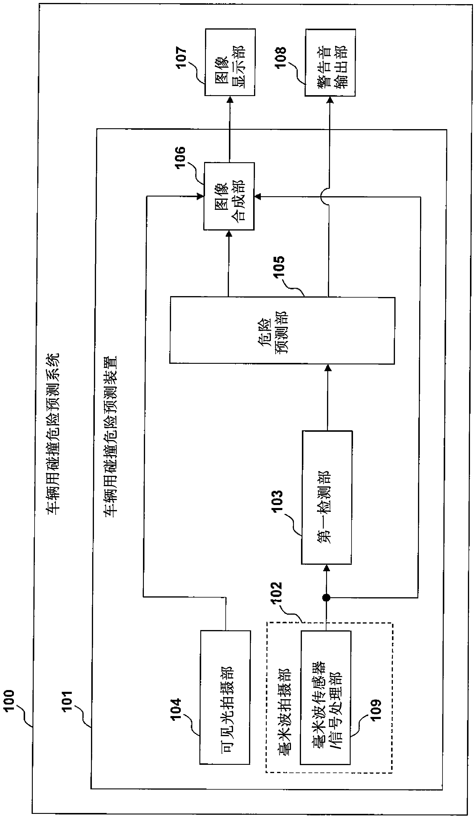
[0161] figure 1 It is a configuration diagram showing the vehicle collision risk prediction system 100 according to the first embodiment of the present invention, and shows a configuration example when the vehicle collision risk prediction device 101 of the present invention is applied to the vehicle collision risk prediction system 100.

[0162] The vehicle collision risk prediction system 100 is a system that is installed in a vehicle and can detect the risk of collision around the vehicle (for example, the front) and issue a warning to the driver.

[0163] The vehicle collision risk prediction system 100 is configured by appropriately using the vehicle collision risk prediction device 101, the image display unit 107, and the warning sound output unit 108.

[0164] The vehicle collision risk prediction device 101 is a device that is installed in a vehicle to detect the risk of a collision around the...

Embodiment 2

[0185] Hereinafter, Example 2 of the present invention will be described in detail.

[0186] Image 6 It is a structural diagram showing a vehicle collision risk prediction system 100-2 of the second embodiment of the present invention, and shows a case where the vehicle collision risk prediction device 101-2 of the present invention is applied to the vehicle collision risk prediction system 100-2 Example of the structure.

[0187] The vehicle collision risk prediction device 101-2 is composed of a millimeter wave imaging unit 102-2, a first detection unit 103-2, a visible light imaging unit 104-2, a danger prediction unit 105-2, and an image synthesis unit 106-2 as appropriate. The wave imaging section 102-2 is configured using a millimeter wave light source 601-2 in addition to the millimeter wave sensor / signal processing section 109-2.

[0188] The millimeter wave light source 601-2 is a light source (emission source) capable of emitting electromagnetic waves (wavelength: about s...

Embodiment 3

[0196] Hereinafter, Embodiment 3 of the present invention will be described in detail.

[0197] Picture 9 It is a configuration diagram showing a vehicle collision risk prediction system 100-3 of the third embodiment of the present invention, and shows a case where the vehicle collision risk prediction device 101-3 of the present invention is applied to the vehicle collision risk prediction system 100-3 Example of the structure.

[0198] The vehicle collision risk prediction device 101-3 is composed of a millimeter wave imaging unit 102-3, a first detection unit 103-3, a visible light imaging unit 104-3, a danger prediction unit 105-3, and an image synthesis unit 106-3 as appropriate. The wave imaging unit 102-3 is configured using a millimeter wave sensor / signal processing unit 109-3 and a millimeter wave light source 601-3.

[0199] The risk prediction unit 105-3 performs the same processing as the risk prediction unit 105-2 of the second embodiment. Furthermore, the danger pred...


PUM


Abstract

In driving of the vehicle, when an object unexpected by a driver suddenly appears at a close range in a traveling direction of the vehicle, a collision is liable to occur. A vehicle risk prediction apparatus includes: a first imaging unit that detects an electromagnetic wave of a wavelength ranging from a millimeter wave to a submillimeter wave to output a first image; a first detection unit that processes the first image output from the first imaging unit to detect a given object; and a risk prediction unit that outputs a detection result of the given object detected by the first detection unit. The first imaging unit includes: a transmit antenna unit that radiates the electromagnetic wave of the wavelength ranging from the millimeter wave to the submillimeter wave; a receive antenna array unit that has a plurality of receive antenna units arranged two-dimensionally, and receives a reflected wave of the electromagnetic wave radiated by the transmit antenna unit from the given object; and a signal processing unit that measures a time from radiation of the electromagnetic wave by the transmit antenna unit to reception of the reflected wave by the receive antenna array unit according to the number of read frames by the receive antenna array, and calculates both or any one of a distance from the subject vehicle to the given object, and a relative speed between the subject vehicle and the given object.

Description

Technical field [0001] The present invention relates to a collision risk prediction device for vehicles. Background technique [0002] Patent Document 1 is a background art in this technical field. The gazette states that "a method for detecting obstacles on the road using millimeter wave sensors installed on the roadside is based on the difference between the measurement data obtained by the millimeter wave sensor scanning and the background data of the obstacles. Object candidates are subject to detection processing, and this processing is repeated, and when there are always obstacle candidates, it is detected as an obstacle" (refer to the manual abstract). [0003] Patent Document 1: Japanese Patent Application Publication No. 2000-172980 Summary of the invention [0004] When a vehicle is running, when an object that the driver cannot predict suddenly appears at a very close distance in the forward direction of the vehicle, a collision may easily occur. For example, in a turn...

Claims


Application Information

Patent Timeline
IPC IPC(8): B60R21/01G01S13/931
CPCH01Q21/061G01S2013/9353G01S13/18H01Q1/3233G01S2013/9375G01S13/931H01Q1/3283G01S2013/9346G01S2013/9342G01S13/867G01S13/581G01S2013/9332G01S2013/9315G01S2013/9318G01S2013/93185G01S2013/932G01S2013/93271
Inventor 石原朋和西泽明仁盐川淳司
Owner HITACHT MAXELL LTD
Why Eureka
Try Eureka