Embedded boosting vacuum thermal pipe heat collection element pressure reduction stagnation protector

A technology of heat collecting element and vacuum heat pipe, which is applied in the field of embedded booster vacuum heat pipe heat collecting element decompression air sun protector, which can solve the problem that the precision cannot work normally and effectively. It can drive the problems of poor consistency and reduced ability to restore the original state, so as to achieve the effects of improved reliability, good size consistency, and reduced heat dissipation power.

Inactive Publication Date: 2014-11-12
方彩琴
View PDF7 Cites 0 Cited by
  • Summary
  • Abstract
  • Description
  • Claims
  • Application Information

AI Technical Summary

Problems solved by technology

Since this patent is not specifically aimed at the heat-collecting elements of gravity heat pipes, it is not very targeted; the bimetal sheet thermal energy conversion drive used in it is originally not consistent with the product, and has the ability to return to its original shape after repeated heat deformation It will be reduced again, and the operating point setting, control variable input, comparison, energy conversion and energy supply and execution functions related to the control system undertaken by it are far from being able to work normally and effectively due to the impact on the accuracy of the possible 20-year design of the heat collecting element. life

Method used


Image

  • Embedded boosting vacuum thermal pipe heat collection element pressure reduction stagnation protector
  • Embedded boosting vacuum thermal pipe heat collection element pressure reduction stagnation protector
  • Embedded boosting vacuum thermal pipe heat collection element pressure reduction stagnation protector

Examples


Embodiment Construction

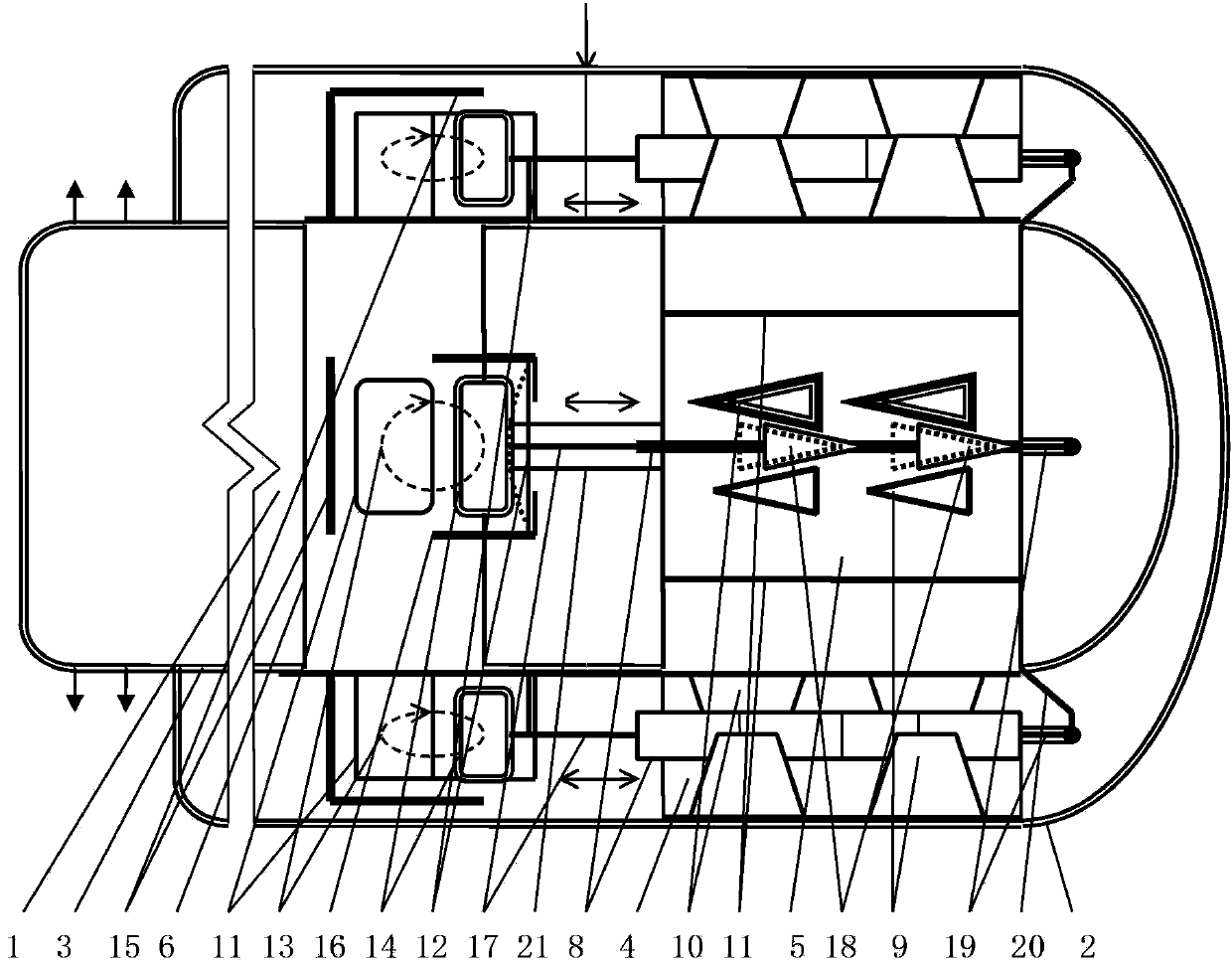
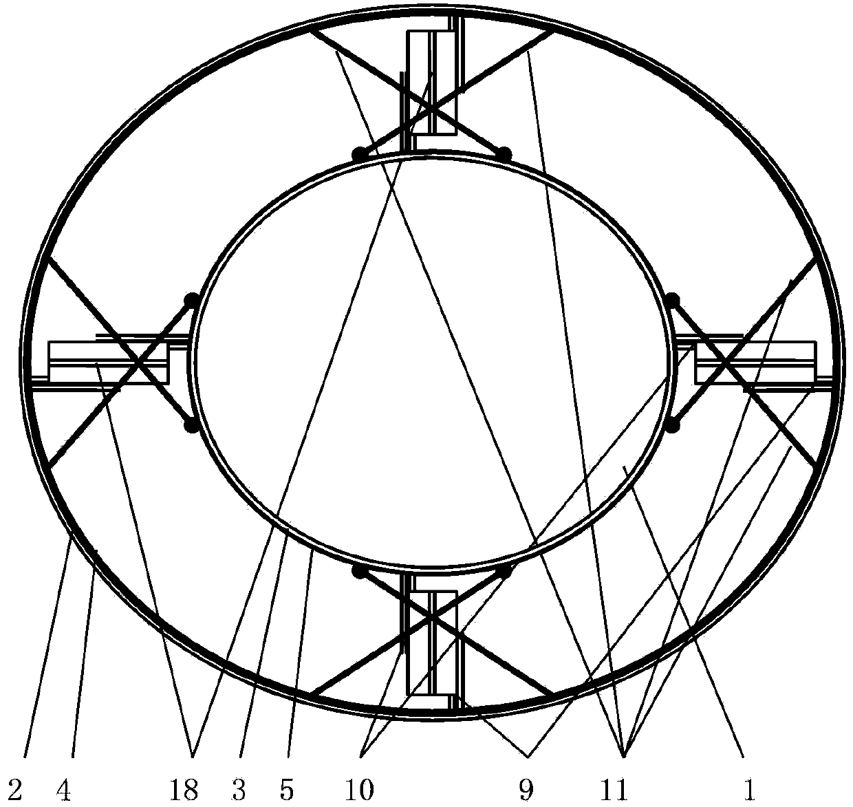
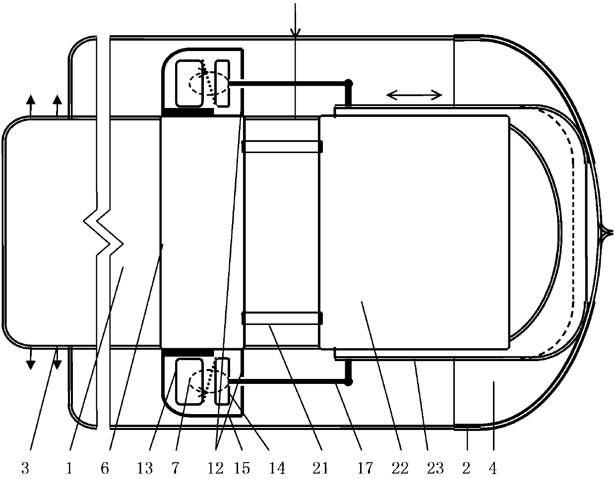
[0041] figure 1 and figure 2 A first embodiment of the present invention is given.

[0042] figure 1 and figure 2 Among them, in the vacuum heat insulation layer between the round end of the cover glass tube 2 of the heat collecting element of the vacuum heat pipe and the inner glass tube 3, that is, the tail end of the heat pipe 1, four booster centers are evenly distributed along the circumference of the annular vacuum heat insulation layer. The heat-collecting element of the vacuum heat pipe is decompressed and air-dried to protect the heat transfer channel, forming an embedded booster in the vacuum heat pipe heat-collecting element decompressed and air-dried protector. The air-drying protection heat transfer channel is composed of a heat dissipation patch 4, a heat absorbing member 5, a heat-sensitive permanent magnet steel drive device 7 with a heat guide 6, and a middle plate 8 connected to the heat-sensitive permanent magnet steel drive device 7 through transmiss...


PUM


Abstract

An embedded boosting vacuum thermal pipe heat collection element pressure reduction stagnation protector is formed by a stagnation protection heat transfer channel comprising a heat radiation patch, a heat absorbing part, a thermal sensitive permanent magnetic steel driver and middle pieces, and is characterized in that the thermal sensitive permanent magnetic steel driver comprises a thermal sensitive permanent magnetic steel soft iron driver pair and a double-metal sheet boosting part; an embedded boosting straight cylinder vacuum thermal pipe heat collection element reduces the pressure of the stagnation protector, is formed by a boosting thermal driver and a heat conduction straight cylinder, and is characterized in that the boosting thermal driver comprises the double-metal sheet boosting part, thermal sensitive permanent magnetic steel and soft iron; and the soft iron is in transmission connection with a heat transfer straight cylinder. The double-metal sheet boosting part helps the thermal sensitive permanent magnetic steel soft iron pair suck when the state of the thermal sensitive magnetic steel is converted from demagnetized into magnetic. The problem that soft iron is too far from the thermal sensitive permanent magnetic steel 8 to normally work is solved. According to the invention, only the low-power stagnation protector can ensure that pressure of steam in the hot pipes is not greater than double atmospheric pressure always, and is high in reliability.

Description

technical field [0001] The invention relates to a decompression air-drying protector for an embedded booster vacuum heat pipe heat collecting element. Background technique [0002] The vacuum heat collecting tube is provided with a vacuum heat insulation layer between its cover glass tube and the inner glass tube, which can manufacture a vacuum solar water heater that can also provide domestic hot water in winter. The solar water heater made of heat pipe vacuum heat collecting tube has the advantages of high energy efficiency ratio without water in the tube, conforms to the sanitary drinking water standard, and can work as usual if a single tube is damaged. therefore. The solar vacuum heat pipe water heater without water in the pipe will likely occupy more and more market share. [0003] The use of an integrated glass heat pipe has the advantages of being melted and sealed with the cover glass tube, the surface of the glass heat pipe can be directly made into an absorption...

Claims


Application Information

Patent Timeline
Patent Type & Authority Patents(China)
IPC IPC(8): F24J2/05F24J2/32F24J2/46F24S10/40F24S10/95
CPCY02E10/44
Inventor 施国樑
Owner 方彩琴
Why Eureka
Try Eureka