
Angle increment optimization method for rolling pendulum seeker tracking loop

A technology of tracking loops and optimization methods, applied in non-electric variable control, position/direction control, instruments, etc., can solve problems such as large input information, rising cost, and complex system

Inactive Publication Date: 2013-07-31
CHANGCHUN INST OF OPTICS FINE MECHANICS & PHYSICS CHINESE ACAD OF SCI
View PDF6 Cites 1 Cited by
  • Summary
  • Abstract
  • Description
  • Claims
  • Application Information

AI Technical Summary

Problems solved by technology

The pitch-azimuth structure seeker usually uses the pitch frame as the inner frame and the azimuth frame as the outer frame. Its advantages are simple and compact, the two channels are independent of each other, less coupling, and the control and tracking algorithms are more mature; the disadvantage is that the spatial structure constraints and the blind zone of large off-axis angles, the off-axis angle of this platform is difficult to break through ±60°
However, the disadvantage of the roll-swing seeker is that there are certain difficulties in extracting and optimizing the control angle position command of the tracking loop
[0004] Among the above three methods, the first two methods require more input information, and there is no numerical multi-solution instruction optimization method for inverse trigonometric functions for specific applications; although the third method proposes instruction optimization criteria, it solves the angle increment process In addition to using the information in the first two methods, the projectile-to-target distance information is also required, which will cause system complexity and cost increase in seeker testing and application

Method used


Image

  • Angle increment optimization method for rolling pendulum seeker tracking loop
  • Angle increment optimization method for rolling pendulum seeker tracking loop
  • Angle increment optimization method for rolling pendulum seeker tracking loop

Examples


Embodiment Construction

[0046] Invention idea of ​​the present invention is:

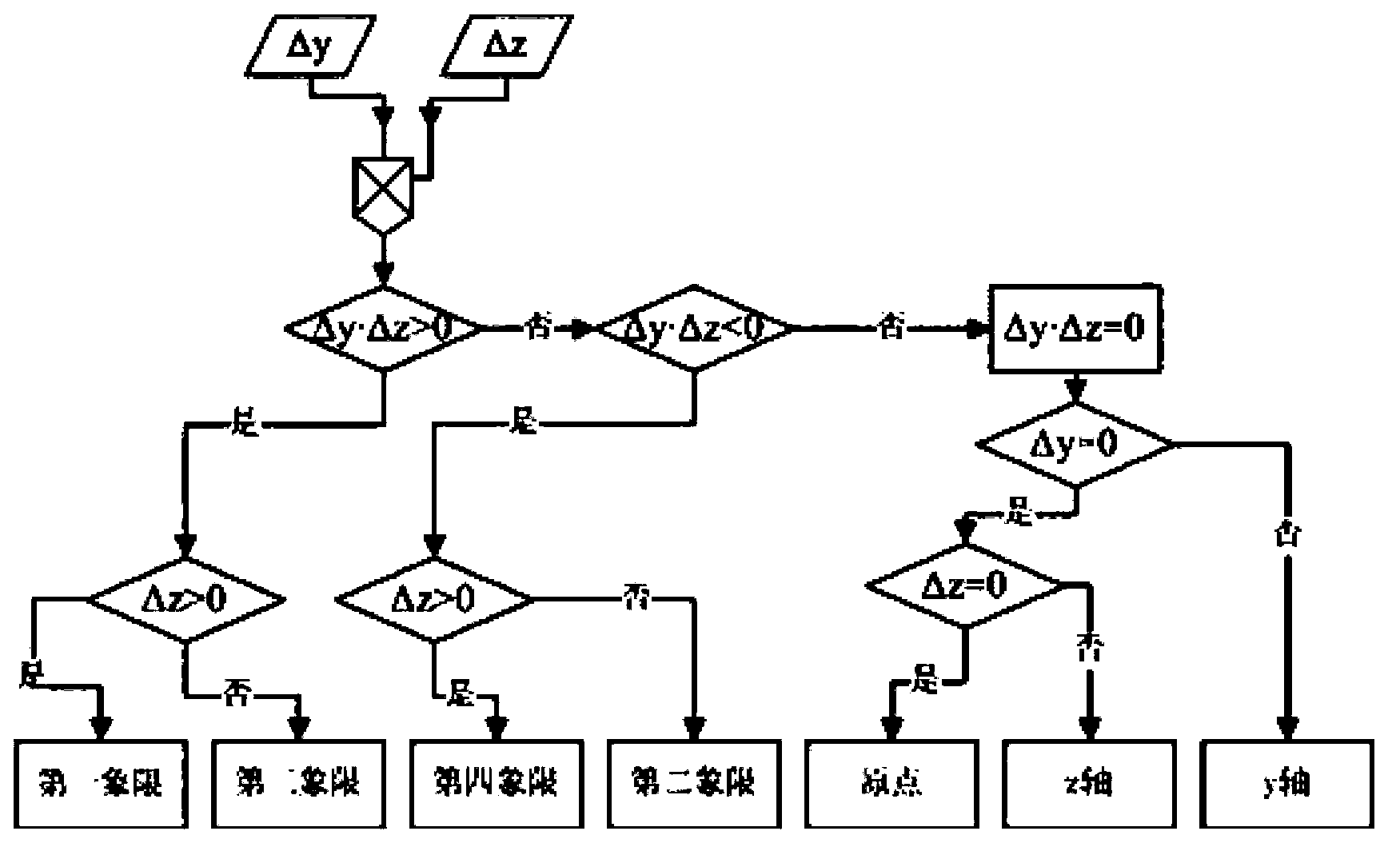
[0047] The commonly used target surface shapes of roll-swing seeker image detectors are rectangular and circular. The bullseye is located at the geometric center of the target surface, and the pixel representation of the coordinate value of the target in the Cartesian coordinate system of the target surface is the amount of miss. According to the coordinate definition of the missile, the horizontal and vertical misses on the target surface are defined as Δy and Δz respectively, and the unit is the number of pixels. The pixel size of the detector is expressed as μ, and the unit is mm. In the case of a relatively small misalignment angle, the control angle increments of the roll and swing frames can be expressed by the arctangent function,

[0048] Δθ r = arctan ...


PUM


Abstract

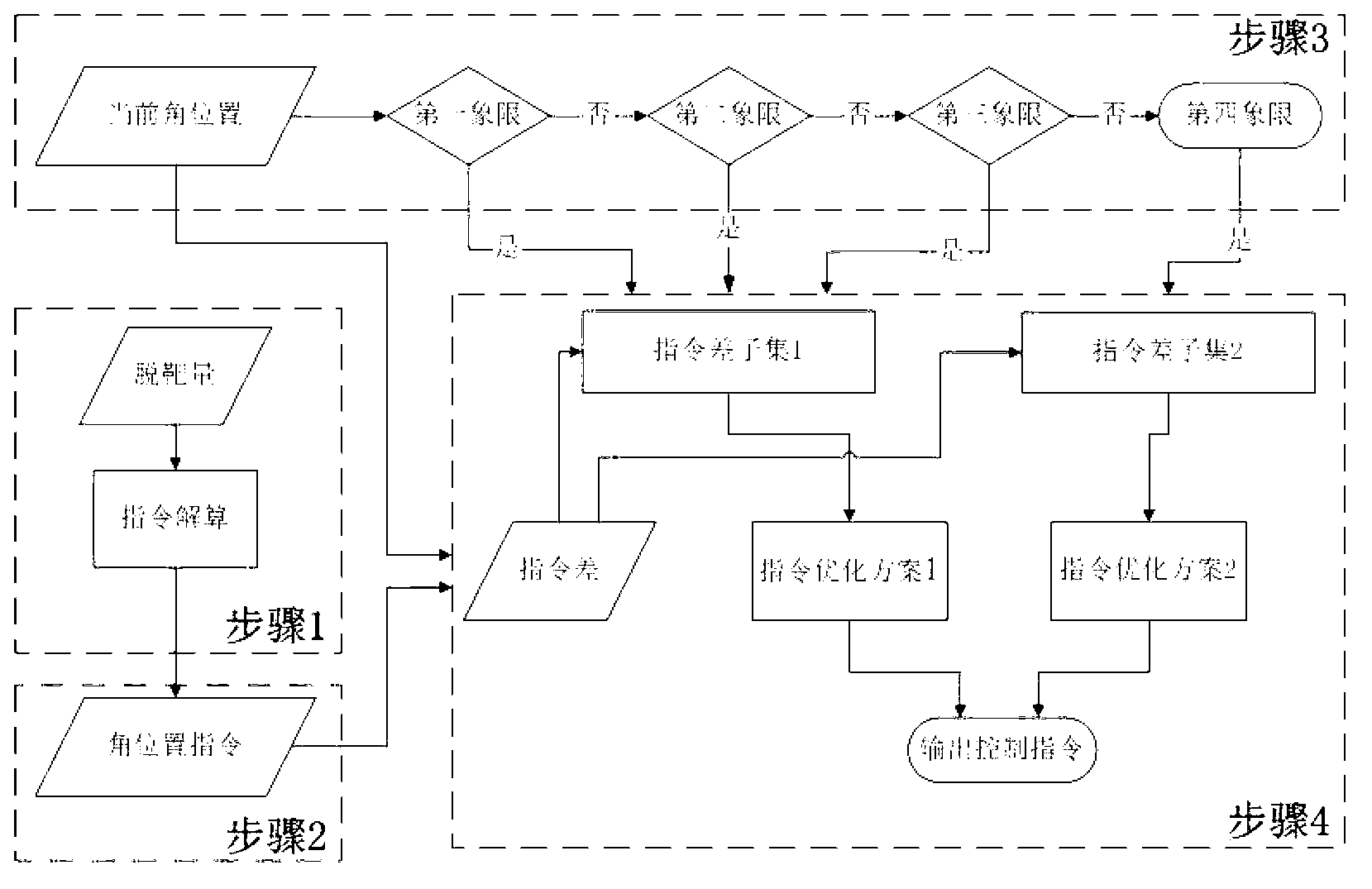
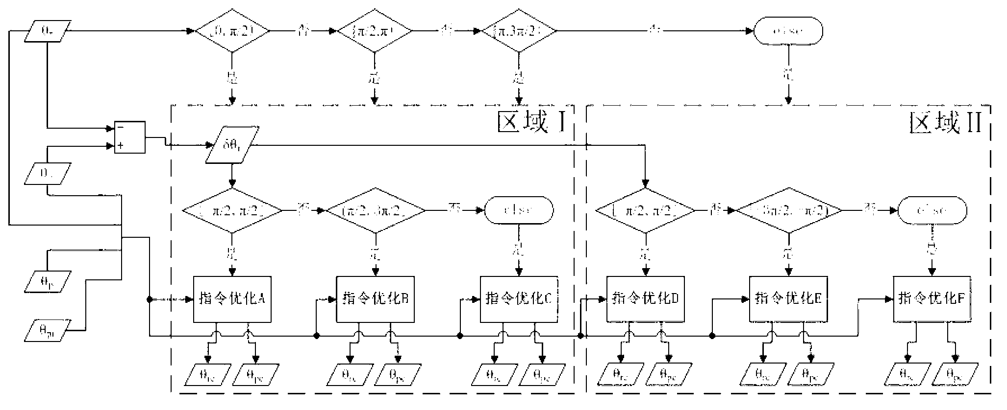
The invention relates to an angle increment optimization method for a rolling pendulum seeker tracking loop, which comprises the following steps that when an absolute value of a relative motion range of a rolling frame is less than or equal to Pi / 2, calculated angle position instructions of the rolling frame and a pendulum frame are outputted directly; when the absolute value of the relative motion range of the rolling frame is (Pi / 2, 3Pi / 2], the angle position instruction of the pendulum frame is minus; the absolute value of the relative motion range of the rolling frame is controlled to be less than Pi / 2; and when the absolute value of the relative motion range of the rolling frame is (3Pi / 2, 2Pi), a limiting condition of the rolling frame is allowed to optimize an output instruction. According to the angle increment optimization method for the rolling pendulum seeker tracking loop, the provided angle position instruction has a definite, single target directional relation in a tracking range of a seeker; a logical relation is clear; a solution process does not require a large number of matrix operations; hardware is light in burden; and the real-time performance is good.

Description

technical field [0001] The invention belongs to the field of design and application of an optical tracking platform servo control system, and in particular relates to a roll-swing type seeker tracking loop angle increment optimization method suitable for a roll-swing structure imaging seeker. Background technique [0002] At present, the commonly used two-axis imaging seeker stabilization platform mostly adopts pitch-azimuth structure and roll-swing structure. The pitch-azimuth structure seeker usually uses the pitch frame as the inner frame and the azimuth frame as the outer frame. Its advantages are simple and compact, the two channels are independent of each other, less coupling, and the control and tracking algorithms are more mature; the disadvantage is that the spatial structure Due to the constraints of the constraints and the blind area of ​​the large off-axis angle, it is difficult for the off-axis angle of this platform to break through ±60°. The seeker stabilized...

Claims


Application Information

Patent Timeline
IPC IPC(8): G05D3/00G05B13/02
Inventor 姜湖海魏群贾宏光王超虞林瑶张天翼朱瑞飞吴海龙
Owner CHANGCHUN INST OF OPTICS FINE MECHANICS & PHYSICS CHINESE ACAD OF SCI
Learn More