Waste gas purification system in rubber processing field

An exhaust gas purification system and a technology in the field, applied in the field of exhaust gas purification systems, can solve the problems of a large amount of tail gas, high moisture content in flue gas, and low desulfurization efficiency, so as to improve the overall intelligence, prolong the running time, and ensure the desulfurization effect Effect

Inactive Publication Date: 2013-08-07
TIANJIN DONGZHEN RUBBER
View PDF6 Cites 15 Cited by
  • Summary
  • Abstract
  • Description
  • Claims
  • Application Information

AI Technical Summary

Problems solved by technology

[0002] In the current mechanical production, such as the regeneration process of butyl rubber, a large amount of high-temperature toxic waste gas mixed with various impurities will be produced. Before the waste gas is discharged, it needs to be purified. The existing purification equipment is generally through a desulfurization purification tower. Use treatment liquid or biological treatment liquid to decompose harmful substances, but a simple purification tower cannot eliminate all harmful components, and it is not conducive to the recovery and utilization of components in toxic gases
[0003] At the same time, the existing purification towers generally use swirl plates, but the traditional planar swirl plates are prone to blockage due to their large resistance. The moisture content of the flue gas after showering is high and the exhaust gas after treatment contains a lot of water mist and other problems

Method used


Image

  • Waste gas purification system in rubber processing field
  • Waste gas purification system in rubber processing field

Examples


Embodiment Construction

[0020] The present invention will be described in further detail below in conjunction with the accompanying drawings and specific embodiments. It should be understood that the specific embodiments described here are only used to explain the present invention, not to limit the present invention.

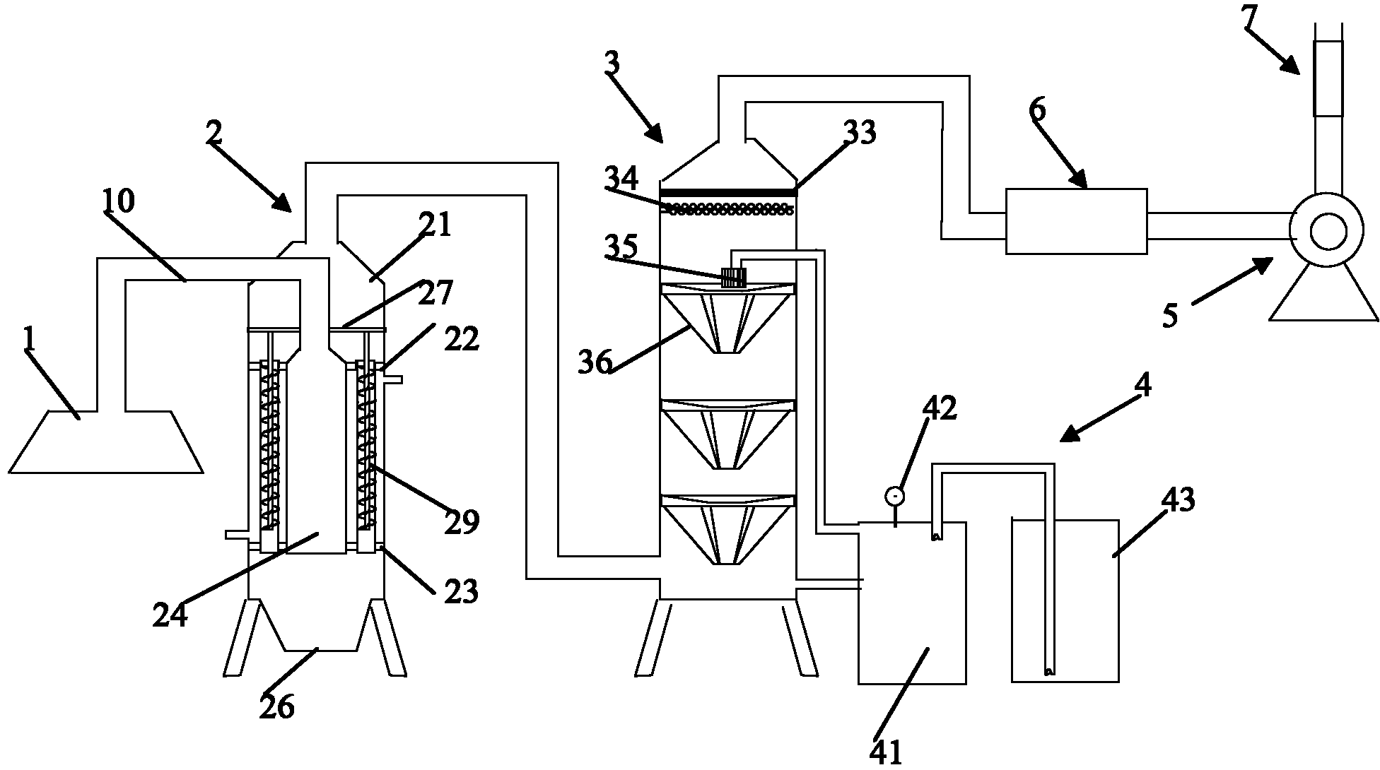
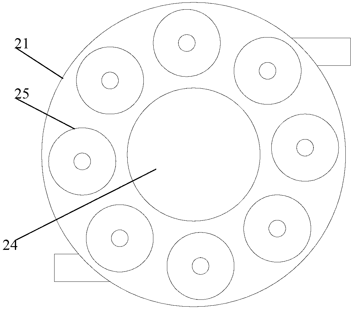
[0021] like figure 1 and 2 As shown, the exhaust gas purification system in the field of rubber processing of the present invention includes a plurality of wind collecting hoods 1 respectively arranged above each station, an additive recovery tower 2 communicating with the wind collecting hoods 1 through the air inlet pipe 10, and The desulfurization and purification tower 3 connected to the exhaust port of the auxiliary agent recovery tower is connected with the exhaust port on the top of the desulfurization purification tower 3, and is used to force the air to enter the wind collecting hood and finally discharge the induced draft fan 5 outside. Activated carbon filter tower or ult...


PUM


Abstract

The invention discloses a waste gas purification system in the rubber processing field. The waste gas purification system comprises a plurality of wind collecting covers, an assistant recovery tower, a desulfurization purification tower, a draught fan, an activated carbon filtration tower or ultraviolet catalytic oxidation waste gas purification apparatus, an oxyhydrogen flame combustor and a treating liquid circulating device, wherein the wind collecting covers are respectively arranged above each working station; the assistant recovery tower is communicated with the wind collecting covers through gas inlet pipes; the desulfurization purification tower is communicated with a gas outlet of the assistant recovery tower; the draught fan is communicated with a gas outlet of the desulfurization purification tower and is used for forcing air into the wind collecting covers and finally discharging to the outside; the activated carbon filtration tower or ultraviolet catalytic oxidation waste gas purification apparatus is connected in series between the desulfurization purification tower and the draught fan; the oxyhydrogen flame combustor is arranged at a wind outlet of the draught fan; and the treating liquid circulating device is used for supplying treating liquid to the desulfurization purification tower. According to the invention, the waste gas purification system in the rubber processing field cools and depressurizes high-temperature waste gas to gradually separate particles and liquid drops included in the waste gas from the waste gas and collect in the collecting covers; and the assistant recovery rate can be up to 70%.

Description

technical field [0001] The invention relates to the technical field of rubber processing, in particular to an exhaust gas purification system in the field of rubber processing. Background technique [0002] In the current mechanical production, such as the regeneration process of butyl rubber, a large amount of high-temperature toxic waste gas mixed with various impurities will be produced. Before the waste gas is discharged, it needs to be purified. The existing purification equipment is generally through a desulfurization purification tower. Use treatment liquid or biological treatment liquid to decompose harmful substances, but a simple purification tower cannot eliminate all harmful components, and it is not conducive to the recovery and utilization of components in toxic gases. [0003] At the same time, the existing purification towers generally use swirl plates, but the traditional planar swirl plates are prone to blockage due to their large resistance. The moisture ...

Claims


Application Information

Patent Timeline
Patent Type & Authority Applications(China)
IPC IPC(8): B01D53/75B01D53/86B01D53/78B01D50/00B01D53/00
Inventor 张大鲁董英利张一眀
Owner TIANJIN DONGZHEN RUBBER
Why Eureka
Try Eureka