Cutter for processing valve seat seal groove

A technology for sealing grooves and tools, applied in the field of processing tools, can solve the problems of low processing efficiency, cumbersome process, complex structure, etc., and achieve the effects of high processing precision, simple tool structure, and simple correction program.

Inactive Publication Date: 2013-08-07
LIUYANG FY HYDRAULIC CYLINDER
View PDF6 Cites 3 Cited by
  • Summary
  • Abstract
  • Description
  • Claims
  • Application Information

AI Technical Summary

Problems solved by technology

[0009] In order to solve the problems of complex structure, cumbersome process and low processing efficiency in the prior art, the present invention provides a cutting tool for valve seat sealing groove processing. The cutting tool has a simple structure, reduces the process of center correction and improves work efficiency

Method used


Image

  • Cutter for processing valve seat seal groove
  • Cutter for processing valve seat seal groove

Examples


Embodiment Construction

[0030] Specific embodiments of the present invention will be described in detail below in conjunction with the accompanying drawings. It should be understood that the specific embodiments described here are only used to illustrate and explain the present invention, and are not intended to limit the present invention.

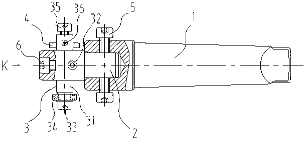
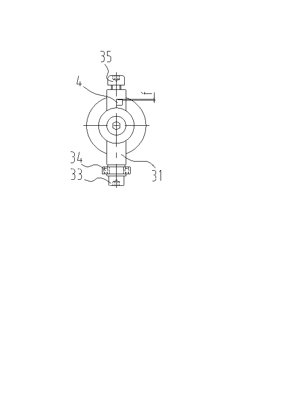
[0031] Such as figure 1 As shown, the cutter includes a knife handle 1, a cutter head 2, a knife bar 3 and a blade 4, one end of the knife head 2 is connected with the knife handle 1, the knife bar 3 is connected with the knife head 2, and the blade 4 is connected with the knife bar 3. The tool has simple structure, low production cost, strong pertinence and good practicability, and can be produced and used by various demand enterprises without professional tool processing equipment. And because the cutter head 2 is provided, the center of the machining hole can be quickly found when the sealing groove of the valve seat is processed, the process of correcting t...


PUM


Abstract

The invention discloses a cutter for processing a valve seat seal groove. The valve seat seal groove comprises a cutter handle (1), a cutter head (2), a cutter rod (3) and a cutter blade (4). One end of the cutter head (2) is connected to the cutter handle (1). The cutter rod (3) is connected to the cutter head (2). The cutter blade (4) is connected to the cutter rod (3). The cutter has a simple structure, avoids a center correction process, and has a high processing precision. Parts processed by the cutter have good size uniformity. The cutter improves processing efficiency by 2-6 times.

Description

technical field [0001] The invention relates to a machining tool, more specifically, to a tool used for machining sealing grooves of valve seats. Background technique [0002] For the valve parts where the hydraulic control valve is directly installed on the hydraulic cylinder, most of the seal installation grooves need to be opened on the valve seat of the hydraulic cylinder. At present, the valve installation plane of the hydraulic cylinder generally adopts the O-ring end face seal form, and this seal groove is generally on the end face of the workpiece and not in the center of the workpiece. When processing such parts, lathe processing is generally used. First, the center of the hole is corrected by positioning the four claws, and then the sealing groove is processed by turning. Due to the limitations of the equipment, this traditional lathe four-jaw method of correcting the center of the sealing groove and then turning the center of the hole is cumbersome, and it is...

Claims


Application Information

Patent Timeline
Patent Type & Authority Applications(China)
IPC IPC(8): B23C5/24B23C3/28
Inventor 凡红弟廖祥珽李昆阳
Owner LIUYANG FY HYDRAULIC CYLINDER
Why Eureka
Try Eureka