Vacuum heat collection element with lever pressure reduction idle sunning protector

A vacuum heat collection and protector technology, which is applied to solar collectors, solar collectors, and heating devices using working fluids, and can solve the problem of reduced ability to restore the original state, poor pertinence, and bimetal heat exchange It can solve problems such as poor consistency of driving parts, and achieve the effects of improving reliability, reducing outgassing, and reducing heat dissipation power

Inactive Publication Date: 2014-12-03
赵钦舫
View PDF5 Cites 0 Cited by
  • Summary
  • Abstract
  • Description
  • Claims
  • Application Information

AI Technical Summary

Problems solved by technology

Since this patent is not specifically aimed at the heat-collecting elements of gravity heat pipes, it is not very targeted; the bimetal sheet thermal energy conversion drive used in it is originally not consistent with the product, and has the ability to return to its original shape after repeated heat deformation It will be reduced again, and the operating point setting, control variable input, comparison, energy conversion and energy supply and execution functions related to the control system undertaken by it are far from being able to work normally and effectively due to the impact on the accuracy of the possible 20-year design of the heat collecting element. life

Method used


Image

  • Vacuum heat collection element with lever pressure reduction idle sunning protector
  • Vacuum heat collection element with lever pressure reduction idle sunning protector
  • Vacuum heat collection element with lever pressure reduction idle sunning protector

Examples


Embodiment Construction

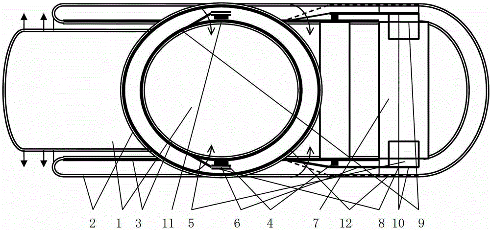
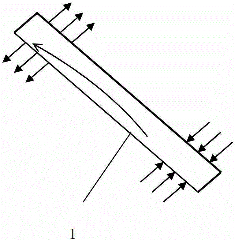
[0031] figure 1 An example of the present invention is given.

[0032] figure 1 Among them, in the vacuum heat insulation layer between the end of the cover glass tube and the end of the inner glass tube of an all-glass vacuum heat collecting tube, two heat-sensitive permanent magnet steel 4, soft iron heat fin 5, and transmission lever are set. 6 and the controllable heat transfer channel formed by connecting the circlips to form a vacuum heat collecting element with a heat fin decompression air drying protector. The soft iron hot fin 5 forms by punching flanging on the heat sink 7, and its movable side 8 is shorter than the fixed side 9. Heat sink 7 is also made with a right-angled connecting clip spring assembly groove to facilitate assembly. The heat sink 7 is rolled into a cylindrical shape with a thin iron plate to wrap the tail end of the inner glass tube 3 with low thermal resistance. One end of transmission lever 6 is fixed, and the middle section is above the h...


PUM


Abstract

Disclosed is a vacuum heat collection element with a lever pressure reduction idle sunning protector. The lever heat fin pressure reduction idle sunning protector is arranged in a vacuum heat insulating layer between the tail end of a cover glass tube of an all-glass vacuum heat collection tube and the tail end of an inner glass tube, the lever pressure reduction idle sunning protector comprises a plurality of controllable heat transfer channels, and each controllable heat transfer channel comprises heat-sensitive permanent magnet steel, a soft iron heat fin, a transmission lever and a connecting clamp spring. The vacuum heat collection element is characterized in that a fixed edge of the soft iron heat fin is connected with the tail end of the inner glass tube by low heat resistance, the middle of the transmission lever is positioned above the heat-sensitive permanent magnet steel, and a free end of the transmission lever extends into the lower side of a movable edge of the soft iron heat fin. When the heat-sensitive permanent magnet steel has / loses magnetism, the transmission lever is attracted to drop by the heat-sensitive permanent magnet steel, so that the transmission lever rises under the action of elastic force and pushes the movable edge of the soft iron heat fin to be connected with the cover glass tube in a downward bending heat-proof / rising heat transfer manner. By the aid of the idle sunning protector with low power, the vacuum heat collection element can ensure that the internal pressure of the heat tube constantly does not exceed two atmospheric pressures, and heat collection cannot be affected.

Description

technical field [0001] The invention relates to a vacuum heat collecting element with a lever decompression air drying protector. Background technique [0002] The vacuum heat collecting tube is provided with a vacuum heat insulation layer between its cover glass tube and the inner glass tube, which can manufacture a vacuum solar water heater that can also provide domestic hot water in winter. The solar water heater made of heat pipe vacuum heat collecting tube has the advantages of high energy efficiency ratio without water in the tube, conforms to the sanitary drinking water standard, and can work as usual if a single tube is damaged. therefore. The solar vacuum heat pipe water heater without water in the pipe will likely occupy more and more market share. [0003] The use of an integrated glass heat pipe has the advantages of being melted and sealed with the cover glass tube, the surface of the glass heat pipe can be directly made into an absorption film, less heat tra...

Claims


Application Information

Patent Timeline
Patent Type & Authority Patents(China)
IPC IPC(8): F24J2/46F24J2/05F24J2/32F24S10/40F24S10/95
CPCY02E10/44
Inventor 施国樑
Owner 赵钦舫
Why Eureka
Try Eureka