Switchgear environment status parameter monitoring device based on ZigBee network

A technology for environmental status and parameter monitoring, applied to measuring devices, instruments, etc., can solve the problems of switch cabinet temperature rise, metal corrosion, easy formation of humid gas, etc., and achieve the effect of compact structure

Inactive Publication Date: 2013-08-07
STATE GRID CORP OF CHINA +2
View PDF4 Cites 10 Cited by
  • Summary
  • Abstract
  • Description
  • Claims
  • Application Information

AI Technical Summary

Problems solved by technology

When the insulation of the conductors in the switchgear is deteriorated, the leakage current of the conductors will increase, which will greatly increase the current flowing through the conductors, and then the temperature in the switchgear will rise sharply.
The ambient humidity in the switch cabinet is one of the important factors affecting the long-term operation of the equipment in the cabinet. Generally, there are certain heating and dehumidification equipment in the switch cabinet, but when the equipment fails, or the humidity increases sharply in a short period of time, it is easy to form damp in the cabinet. Gas, and condenses into water on the surface of various equipment inside the shell. The structure of the equipment is easy to accelerate aging or cause metal corrosion under the joint action of water vapor and temperature, which has an important impact on the insulation performance.

Method used


Image

  • Switchgear environment status parameter monitoring device based on ZigBee network
  • Switchgear environment status parameter monitoring device based on ZigBee network
  • Switchgear environment status parameter monitoring device based on ZigBee network

Examples


Embodiment Construction

[0022] In order to enable those skilled in the art to better understand the technical solutions of the present invention, the specific implementation manners thereof will be described in detail below with reference to the accompanying drawings:

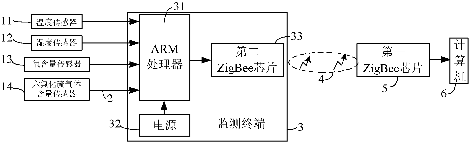
[0023] See figure 1 The switchgear environment parameter monitoring device based on the ZigBee network of the present invention includes several sensors, a multi-core cable 2, a monitoring terminal 3, a ZigBee wireless network 4, a first ZigBee chip 5 and a computer 6, each sensor passing through a multi-core cable 2 Connected to the monitoring terminal 3; the monitoring terminal 3 performs data transmission with the computer 6 through the ZigBee wireless network 4; each sensor includes a temperature sensor 11, a humidity sensor 12, an oxygen sensor 13 and a sulfur hexafluoride gas sensor 14; the monitoring terminal 3 includes ARM processing The power supply 32 and the second ZigBee chip 33 are connected to the ARM processor 31; the first...


PUM


Abstract

The invention discloses a switchgear environment status parameter monitoring device based on a ZigBee network. The switchgear environment status parameter monitoring device comprises a plurality of sensors, multi-core cables, a monitoring terminal, a ZigBee wireless network, a first ZigBee chip and a computer. The sensors are connected with the monitoring terminal through the multi-core cables. The monitoring terminal comprises an ARM (advanced RISC machines) processor, a power source and a second ZigBee chip. The power source and the second ZigBee chip are both connected with the ARM processor. The first ZigBee chip is connected with the computer. The first ZigBee chip and the second ZigBee chip are connected through the ZigBee wireless network. The monitoring terminal is used for performing data transmission with the computer through the ZigBee wireless network. The switchgear environment status parameter monitoring device is compact in structure, the monitoring terminal is of a fixing mount type, the mount structure has no affection on existing design of the switchgear, and the environment status parameter of the switchgear can be effectively monitored on site.

Description

Technical field [0001] The invention relates to a switchgear environmental state parameter monitoring device based on a ZigBee network, which belongs to the technical field of power equipment state monitoring. Background technique [0002] With the rapid development of my country’s power industry, modern power systems are developing in the direction of large power grids, large units, ultra-high voltage, and large capacity. In order to ensure the stability and reliability of the power system, the safety of power equipment has also been improved. High demands. [0003] In recent years, switch cabinets have been widely used in urban power grids. Once a certain defect occurs in the switch cabinet equipment, equipment failures are extremely likely to occur. With the increase in the number of switchgear substations, the probability of failure of switchgear equipment is also increasing. In the past, people thought that switchgear equipment was maintenance-free equipment, and the number o...

Claims


Application Information

Patent Timeline
Patent Type & Authority Applications(China)
IPC IPC(8): G01D21/02
Inventor 施伟国黄成军薛明郭灿新
Owner STATE GRID CORP OF CHINA
Why Eureka
Try Eureka