
Two-dimensional plasma photonic crystal band gap control method

A plasma and photonic crystal technology, applied in the field of control of the band gap formation of microwave devices, can solve the problems of complex methods, high model size and distribution requirements

Inactive Publication Date: 2013-08-07
JIANGSU UNIV
View PDF3 Cites 5 Cited by
  • Summary
  • Abstract
  • Description
  • Claims
  • Application Information

AI Technical Summary

Problems solved by technology

This method is complicated, and the bandgap of the plasmonic photonic crystal can only be controlled by changing the arrangement of the transistors, and the requirements for the size and distribution of the model are relatively high

Method used


Image

  • Two-dimensional plasma photonic crystal band gap control method
  • Two-dimensional plasma photonic crystal band gap control method
  • Two-dimensional plasma photonic crystal band gap control method

Examples


Embodiment Construction

[0020] The technical solution of the present invention will be described in further detail below according to the accompanying drawings.

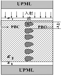
[0021] like figure 1 As shown, the basic flow of modeling of plasmonic photonic crystals is as follows

[0022] Step (1) Establish a rectangular solid model for a single cell using the finite-difference method in time domain. coincidence, the dielectric constant ε of the model background medium 2 Greater than 0.

[0023] Step (2) uniformly embed N identical plasma media in the background medium, and the dielectric constant of the plasma media is denoted as ε 3 .

[0024] Step (3) In the rectangular solid model of a single cell, the outer sides of the two opposite sides that have a gap with the background medium of the rectangular model are close to the opposite sides, and the UPML absorption boundary is added respectively, and the dielectric constant is filled between the absorption boundary and the background medium...


PUM


Abstract

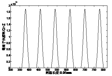
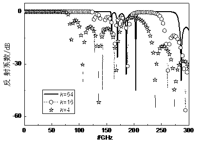
The invention discloses a two-dimensional plasma photonic crystal band gap control method, which comprises the steps of establishing a two-dimensional plasma photonic crystal model and obtaining the magnitude of the band gap of a two-dimensional plasma photonic crystal by using the reflection coefficient of the model; and expressing plasma frequency by using a Gaussian pulse function, and adjusting and controlling the magnitude of the band gap of the two-dimensional plasma photonic crystal through the variation of the expression of the Gaussian pulse function. By adopting the technical scheme provided by the invention, the distribution of the model is not required to be changed, the control of the band gap of the two-dimensional plasma photonic crystal is realized by changing the magnitude of the plasma frequency, the control method is simple, easy and direct and the requirement on the model is low. The two-dimensional plasma photonic crystal band gap control method is applicable to the adjustment and the control of the band gap of the plasma photonic crystal under the situation of high frequency.

Description

technical field [0001] The invention belongs to the field of microwave devices, and in particular relates to a method for controlling the formation of forbidden bands of microwave devices. Background technique [0002] Plasma photonic crystals refer to artificial periodic structures in which plasma and medium are arranged in a periodic structure. It is a special branch of photonic crystals. It not only has the physical properties of general photonic crystals, but also has The characteristics mainly include: photonic bandgap characteristics, photon localization characteristics and optical characteristics. Among them, the bandgap characteristics of photons have attracted people's attention. In optics, plasmonic photonic crystals also have their own unique properties, and have potential applications in microwave filters, plasma antennas, and plasma lenses. [0003] The application (patent) No. CN200410016099.0 for the invention of "A Method for Adjusting the Bandgap of T...

Claims


Application Information

Patent Timeline
IPC IPC(8): G02B6/122H05H1/24G02F1/01
Inventor 杨利霞陈伟施卫东许红蕾郑晶
Owner JIANGSU UNIV
Learn More