
Inductive coupling type high-frequency electrodeless lamp simulation device and method

A technology of inductive coupling and simulation devices, which is applied in the direction of instruments, simulators, control/regulation systems, etc., can solve the problems of high development cost, large difference in working status of electrodeless lamps, and inability to adjust parameters online, so as to achieve reliable technical guarantee, The effect of shortening the development cycle and improving the quality of development

Inactive Publication Date: 2015-06-17
NORTHEASTERN UNIV LIAONING
View PDF4 Cites 0 Cited by
  • Summary
  • Abstract
  • Description
  • Claims
  • Application Information

AI Technical Summary

Problems solved by technology

[0002] At present, manufacturers of electrodeless lamps adopt traditional development methods in the process of developing new products of electrodeless lamps, that is, mainly based on physical testing and testing. When testing or verifying certain design parameters, the electrodeless lamp is not easy to light up, and even the control device is damaged. Development costs are too high
In addition, the kind of electrodeless lamp Reality The experiment cannot easily modify the parameters and observation status, and some parameters cannot be adjusted online
Due to the limitations of physical test methods, the coexistence and conversion of multiple physical fields, and the dispersion of optical, electrical, and magnetic parameters, it is difficult to reproduce the working situation of the electrodeless lamp, and it is not easy to accurately grasp the indicators, which makes the working status of the electrodeless lamp quite different from the theoretical indicators.
[0003] The new method suitable for the actual research and development of electrodeless lamps has not seen relevant reports, and it is a blank situation

Method used


Image

  • Inductive coupling type high-frequency electrodeless lamp simulation device and method
  • Inductive coupling type high-frequency electrodeless lamp simulation device and method
  • Inductive coupling type high-frequency electrodeless lamp simulation device and method

Examples


Embodiment Construction

[0040] An embodiment of the present invention will be further described below in conjunction with the accompanying drawings.

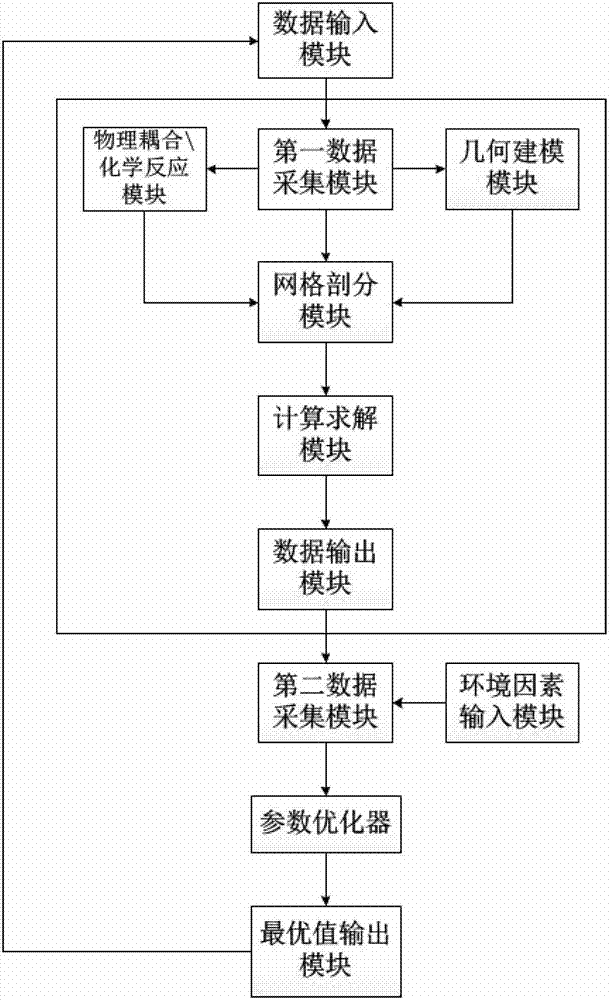
[0041] An inductively coupled high-frequency electrodeless lamp simulation device, such as figure 1As shown, it includes data input module, first data acquisition module, geometric modeling module, physical coupling\chemical reaction module, grid subdivision module, calculation and solution module, data output module, environmental factor input module, and second data acquisition module , parameter optimizer and optimal value output module, which are used to set the geometric shape of the electrodeless lamp (olive, pear, ring, spherical), bulb diameter, bulb material, coupling coil diameter, coil turns, coupling rod Length, power, frequency, voltage, initial electron density, cold junction temperature and magnetic field establishment time, and judge the computer grammar rules of the above parameters, if the parameters conform to the grammar rules, the...


PUM


Abstract

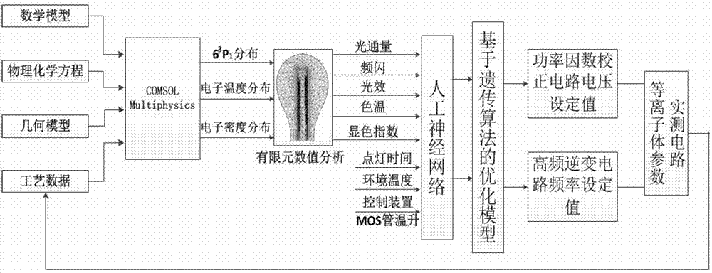
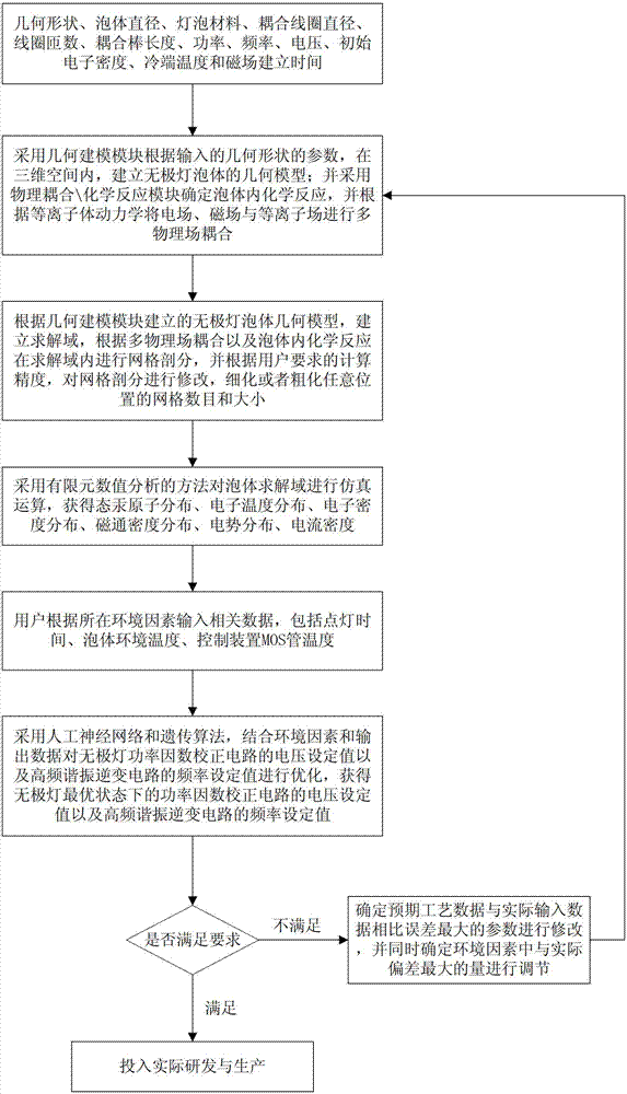
The invention discloses an inductive coupling type high-frequency electrodeless lamp simulation device and method, which belong to the field of lighting engineering. The device comprises a data input module, a first data acquisition module, a geometric modeling module, a physical coupling\chemical reaction module, a mesh generation module, a calculating and solving module, a data output module, an environmental factor input module, a second data acquisition module, a parameter optimization device and an optimal value output module. The device is based on mathematical physics, chemical equations and finite element numerical analysis models, multiple physical fields such as electrical, magnetic and plasma fields of a high-frequency electrodeless lamp are built, realized and optimized so as to guide the electrodeless lamp research and development; a mechanism model and a computer are applied to simulate, so that the development cost is lowered, the development period is shortened, the development quality is improved, the whole electrodeless lamp development process is assisted by the computer, the electrodeless lamp development process is improved from imitation, practicality experiment and data accumulation processes, and reliable technical guarantee is provided for the batch production of the electrodeless lamp.

Description

technical field [0001] The invention belongs to lighting engineering, in particular to an inductively coupled high-frequency electrodeless lamp simulation device and method. Background technique [0002] At present, manufacturers of electrodeless lamps adopt traditional development methods in the process of developing new products of electrodeless lamps, that is, mainly based on physical testing and testing. When testing or verifying certain design parameters, the electrodeless lamp is not easy to light up, and even the control device is damaged. Development costs are too high. In addition, the kind of electrodeless lamp Reality Experiments cannot easily modify parameters and observation status, and some parameters cannot be adjusted online. Due to the limitations of physical test methods, the coexistence and conversion of multiple physical fields, and the dispersion of optical, electrical, and magnetic parameters, it is difficult to reproduce the working situation of the ...

Claims


Application Information

Patent Timeline
Patent Type & Authority Patents(China)
IPC IPC(8): G05B17/02
Inventor 周玮冯禹铭徐宁奚文龙
Owner NORTHEASTERN UNIV LIAONING
Learn More