

Datum point positioning method based on machine vision
A technology of machine vision and positioning method, which is applied in the field of image processing, and can solve the problems of poor positioning accuracy and high cost of the reference point of surface mount equipment
Inactive Publication Date: 2013-08-07
HARBIN INST OF TECH
View PDF4 Cites 63 Cited by
- Summary
- Abstract
- Description
- Claims
- Application Information
AI Technical Summary
Problems solved by technology
Method used
View moreImage
Smart ImageViewing Examples


Examples
specific Embodiment approach 1
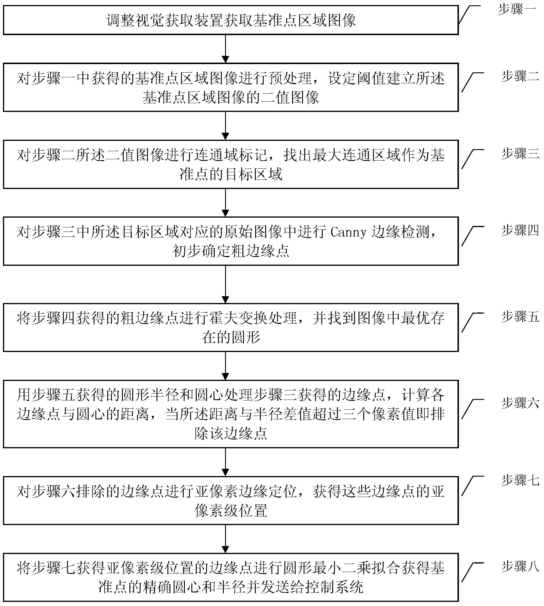
[0054] Specific implementation mode 1. Combination figure 1 This specific embodiment will be described. The fiducial point positioning method based on machine vision includes the following steps:
[0055] Step 1: Adjust the visual acquisition device to acquire the image of the reference point area;
[0056] Step 2: Preprocessing the reference point region image obtained in step 1, setting a threshold to establish a binary image of the reference point region image;
[0057] Step 3: Carry out connected region marking on the binary image described in step 2, and find out the target region with the largest connected region as the reference point;
Login to View More PUM
 Abstract
The invention relates to a datum point positioning method based on machine vision, which belongs to the field of image processing and aims to solve the problems of poor datum point positioning accuracy and high cost of surface mounting equipment. The method comprises the following steps that a vision obtaining device is adjusted to obtain a datum point regional image; the image is preprocessed, and a threshold is set to establish a binary image; connected region labeling is performed on the binary image, so as to find out the largest connected region as a target region of a datum point; Canny edge detection is performed on an original image, so as to preliminarily determine coarse edge points; Hough transformation processing is performed on the coarse edge points, and an optimal existing circle in the image is found out; the distance between each edge point and the center of the circle is calculated; the position of a sub-pixel level of the edge point is obtained; and circular least-square fit is performed on the edge point in the position of the sub-pixel level, and then an accurate center and radius of the datum point are obtained and sent to a control system. The datum point positioning method can be widely applied to accurate positioning of the datum point.
Description
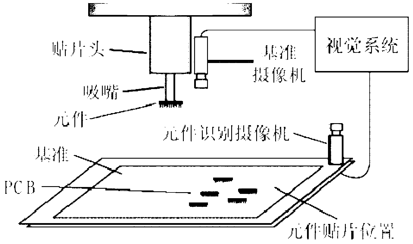
technical field [0001] The invention is applied to a visual method for positioning a reference point on a surface mount device commonly known as a mounter, and belongs to the field of image processing. Background technique [0002] The rapid development of electronic technology has made large-scale integrated circuits and ultra-large-scale integrated circuits widely used, and it has also prompted electronic components to become smaller and thinner and thinner and formatted in storage systems, and it has also driven electronic assembly technology. rapid development. So surface mount technology (Surface Mount Technology, SMT) came into being. An important process of surface mount technology is the surface assembly process, including how to apply solder paste, how to accurately determine the pick-up and placement position of components, how to quickly and accurately place components, how to solder components in a certain position, etc.; The precise positioning of the chip mac...
Claims
Login to View More Application Information
Patent Timeline
 Patent Type & AuthorityApplications(China)
IPC IPC(8): G06K9/00G06T7/00G06T7/60
Inventor高会军张世浩汪超于金泳
OwnerHARBIN INST OF TECH