
A multi-step phase-shift phase detection method with modulation error self-elimination function

A phase detection and modulation error technology, applied in the field of multi-step phase shift phase detection, can solve problems such as the influence of modulation amplitude, and achieve the effects of low hardware system requirements, simple optical path, and improved demodulation accuracy

Active Publication Date: 2021-11-30
NANTONG UNIVERSITY
View PDF5 Cites 0 Cited by
  • Summary
  • Abstract
  • Description
  • Claims
  • Application Information

AI Technical Summary

Problems solved by technology

[0004] In view of this, the object of the present invention is to provide a multi-step phase-shift phase detection method with modulation error self-elimination function, which solves the shortcoming that the traditional rectangular pulse binary phase modulation method is easily affected by the modulation amplitude by realizing the modulation error self-elimination , while improving the resistance to noise and system errors by using a multi-step phase shift algorithm

Method used


Image

  • A multi-step phase-shift phase detection method with modulation error self-elimination function
  • A multi-step phase-shift phase detection method with modulation error self-elimination function
  • A multi-step phase-shift phase detection method with modulation error self-elimination function

Examples


Embodiment 1

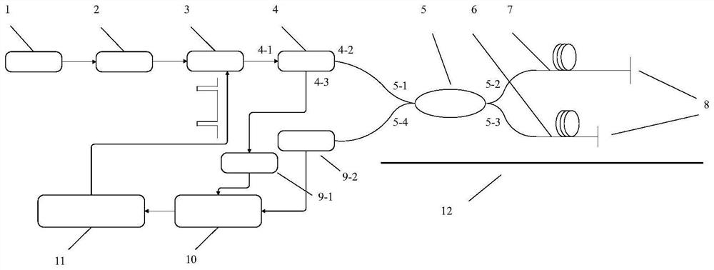
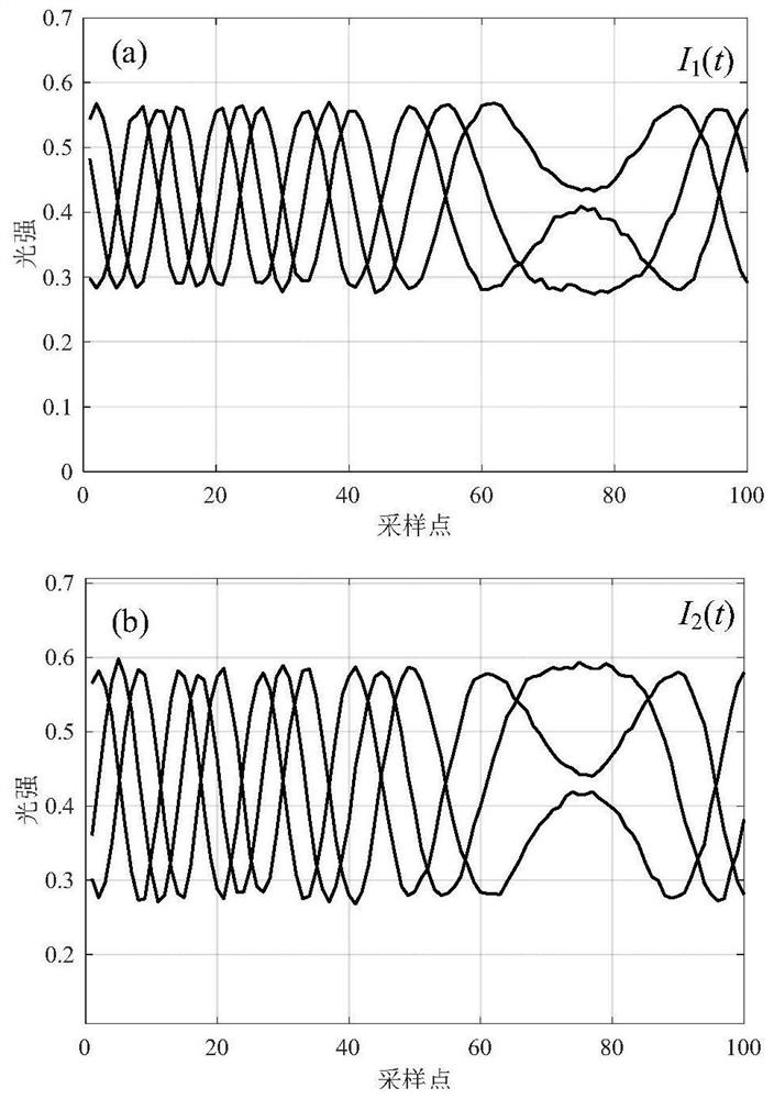
[0056] Experimentally tested the vibration information of a standard sensor at 200Hz, the length difference between the reference arm 6 and the signal arm 7 is 2.8m, the frequency of the high-speed rectangular pulse is 1MHz, and the pulse width modulated in one cycle is 28ns. figure 1 The measurement steps of the multi-step phase-shift phase detection device shown are:

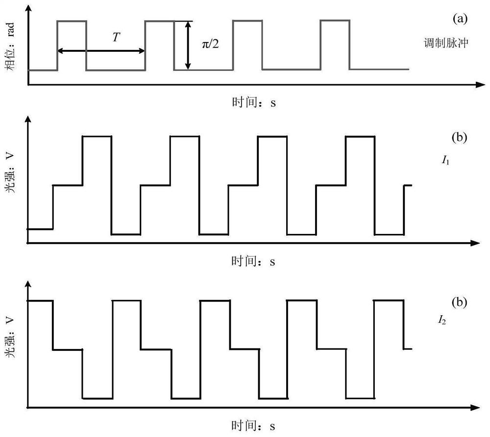
[0057] Step 1. Turn on the micro-vibration table 12, and the micro-vibration table 12 performs sinusoidal regular vibration at 200 Hz. Turn on the laser light source 1, the light emitted by the laser light source 1 passes through the isolator 2 and the phase modulator 3 in sequence, the data processing module 11 generates a rectangular pulse modulation signal with a frequency of 1 MHz, and provides the phase modulator 3 with a modulation amount of π / 2 modulation to form a phase-modulated laser beam;

[0058] Step 2. The phase-modulated laser beam passes through the circulator 4 and the 2×2 coupler 5, and ente...


PUM


Abstract

The invention discloses a multi-step phase-shift phase detection method with the function of self-elimination of modulation errors, which comprises a laser light source, an isolator, a phase modulator, a circulator, a 2×2 coupler, a reference arm, a signal arm, and a Faraday rotator , two photoelectric converters, a data acquisition module, a data processing module and a micro-vibration table. In this method, the rectangular pulse binary phase modulation is performed on the laser light source, and the characteristics of the circulator and the 2×2 coupler are used to generate multiple phase-shifting signals at the output end of the optical fiber sensor, and the cross-correlation operation judgment is performed on two of the output signals. Phase delay amount, automatically adjust the phase modulation drive voltage according to the result to make the phase shift amount π / 2, eliminate the modulation error, and then realize the phase demodulation of the optical fiber sensor according to the multi-step phase shift algorithm. The method can effectively realize the self-elimination of modulation errors and improve the demodulation accuracy, has strong ability to suppress noise and system errors, relatively simple optical path, low hardware system requirements, and fast solution speed.

Description

technical field [0001] The invention belongs to the technical field of optical fiber sensing, and in particular relates to a multi-step phase-shift phase detection method with the function of self-elimination of modulation errors. Background technique [0002] With the improvement of optical fiber technology and optical fiber communication technology, the optical fiber sensing technology using optical fiber as the light transmission medium or sensing medium has been vigorously developed, and has been widely used in military, national defense, civil and other fields. Security, stability and economic development are guaranteed. Optical fiber sensors have a wide range of measurements and can be used to measure physical quantities such as pressure, temperature, vibration, and displacement. Compared with traditional electromagnetic sensors, optical fiber sensors have many advantages such as light weight, strong anti-electromagnetic interference ability, high sensitivity, safety ...

Claims


Application Information

Patent Timeline
Patent Type & Authority Patents(China)
IPC IPC(8): G01J9/02G01H9/00G01D5/353
CPCG01D5/35303G01H9/004G01J9/02G01J2009/0226
Inventor 任仲杰姚佳辰黄云霞杨晓华
Owner NANTONG UNIVERSITY
Learn More