Supercharge Your Innovation With Domain-Expert AI Agents!

Bootstrap dual-input direct current converter

A DC converter and dual-input technology, which is applied in the direction of converting DC power input to DC power output, output power conversion devices, instruments, etc., can solve the problem of system shutdown, increased input source load, and voltage and current that cannot meet safe operation requirements and other problems, to achieve the effect of improving utilization rate and simple structure

Inactive Publication Date: 2015-03-25
YANSHAN UNIV
View PDF3 Cites 0 Cited by
  • Summary
  • Abstract
  • Description
  • Claims
  • Application Information

AI Technical Summary

Problems solved by technology

However, the current research on non-isolated multi-input converters is limited to the fact that energy can be transferred between the input source and the load, and energy cannot be directly transferred between the input sources.
In addition, once a certain input source quits working, it will either increase the load of other input sources, or make the voltage and current on the load unable to meet the safe operation requirements, causing the system to stop, and even damage the equipment in severe cases.
Therefore, the stability and flexibility of this type of topology are not strong, the utilization rate of new energy is not very high, and the application range is relatively limited. Therefore, it is of great significance to seek a topology that can flow energy in multiple directions.

Method used


Image

  • Bootstrap dual-input direct current converter
  • Bootstrap dual-input direct current converter
  • Bootstrap dual-input direct current converter

Examples


Embodiment Construction

[0021] The present invention will be further described below in combination with the accompanying drawings and specific embodiments.

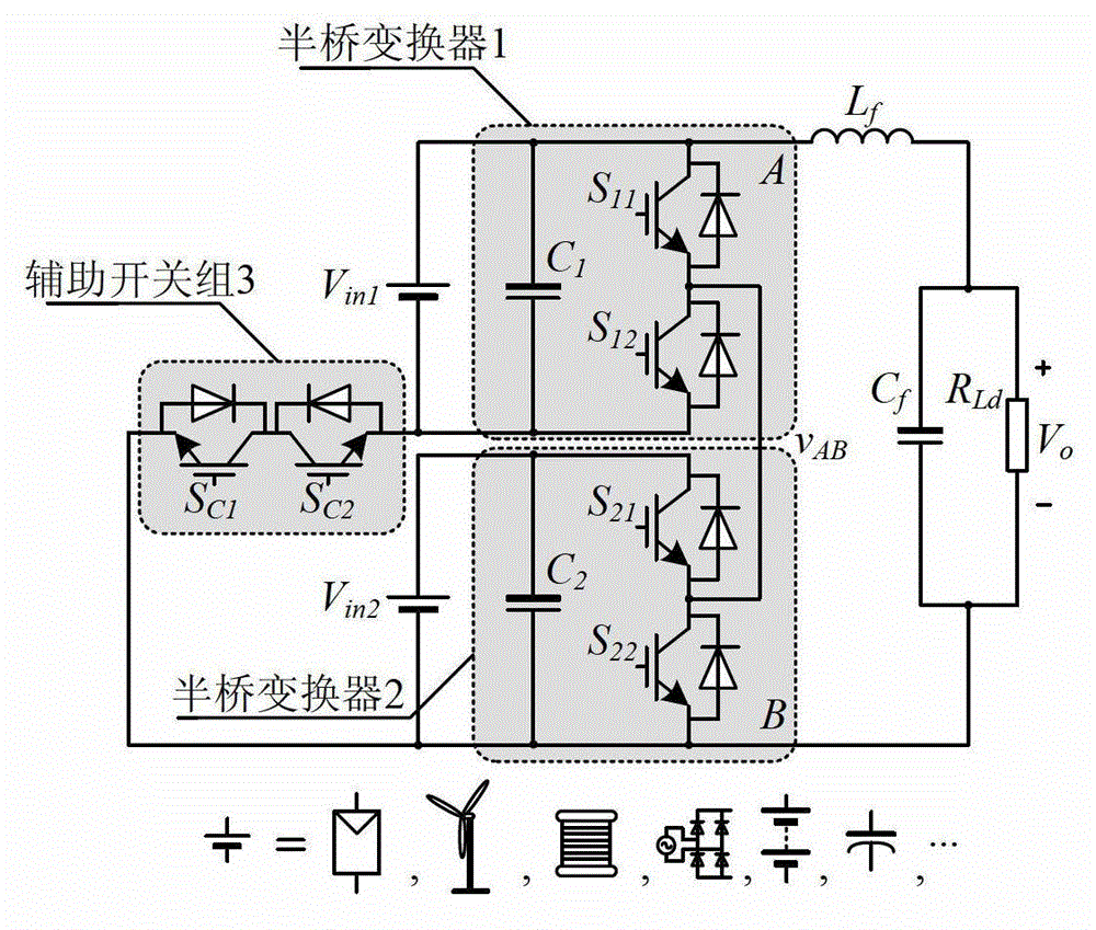
[0022] Such as image 3 As shown, a bootstrap dual-input DC-DC converter includes a half-bridge converter 1, a half-bridge converter 2, and an auxiliary switch group 3; the half-bridge converter 1 is: the input source V in1 Parallel capacitance C 1 , capacitance C 1 The positive pole of the main switch S 11 collector, the capacitor C 1 The negative pole of the main switch S 12 the emitter of the main switch S 11 The emitter is connected to the main switch S 12 collector; half-bridge converter 2 is: input source V in2 Parallel capacitance C 2 , capacitance C 2 The positive pole of the main switch S 11 collector, the capacitor C 2 The negative pole of the main switch S 22 the emitter of the main switch S 21 The emitter is connected to the main switch S 22 collector of the main switch S 11 The emitter is connected to the main switch...


PUM


Abstract

A bootstrap dual-input direct current converter comprises a half-bridge converter 1, a half-bridge converter 2, and an auxiliary switch block 3. An input source Vin1 of the half-bridge converter 1 is connected with a capacitor C1 in parallel. An anode of the capacitor C1 is connected with a collector of a master switch S11. A cathode of the capacitor C1 is connected with an emitter of a master switch S12. An emitter of the master switch S11 is connected with a collector of the master switch S12. An input source Vin2 of the half-bridge converter 2 is connected with a capacitor C2 in parallel. An anode of the capacitor C2 is connected with a collector of the master switch S21. A cathode of the capacitor C2 is connected with an emitter of the master switch S22. An emitter of the master switch S21 is connected with a collector of the master switch S22. The emitter of the master switch S11 is connected with the emitter of the master switch S21. The auxiliary switch block 3 comprises two switch tubes SC1 and SC2. The switch tubes SC1 and SC2 are connected through a common collector. An emitter of the switch tube SC1 is connected with the emitter of the master switch S22. An emitter of the switch tube SC2 is connected with the emitter of the master switch S12. The collector of the switch tube SC1 serves as an output anode of the converter, and the emitter of the switch tube SC2 serves as an output cathode of the converter.

Description

technical field [0001] The invention relates to the technical field of power electronic conversion, in particular to a bootstrap double-input DC converter. Background technique [0002] The electric energy from the primary energy conversion is often not directly utilized by the equipment, and usually undergoes a first-level power electronic conversion, so the power electronic converter plays a pivotal role in the entire energy conversion process. Power electronic converter is a general term for a system composed of power electronic devices and their drive circuits, conductive busbars, monitoring instruments and control circuits, which can complete power conversion. Power electronic devices perform on-off control to make the output power meet the load requirements. [0003] With the increasing demand for electricity, the large-scale exploitation and utilization of fossil energy has made the world's energy situation increasingly tense. At the same time, the large amount of wa...

Claims


Application Information

Patent Timeline
IPC IPC(8): H02M3/155
Inventor 孙孝峰王炜王宝诚李昕
Owner YANSHAN UNIV
Features
  • R&D
  • Intellectual Property
  • Life Sciences
  • Materials
  • Tech Scout
  • Unparalleled Data Quality
  • Higher Quality Content
  • 60% Fewer Hallucinations
Learn More