Equipment and method for cutting and selecting valves and valve leaflets

A leaflet and valve technology, which is applied in valve leaflet cutting equipment and cutting field, can solve the problems of low yield and poor quality of valve leaflets, etc., and achieve the effect of ideal texture direction, controllable thickness and simple structure

Active Publication Date: 2013-08-14
KINGSTRONBIOCHANGSHU CO LTD
View PDF7 Cites 7 Cited by
  • Summary
  • Abstract
  • Description
  • Claims
  • Application Information

AI Technical Summary

Problems solved by technology

[0004] The purpose of the present invention is to propose a valve leaflet cutting device to achieve simple structure and high quality of valve leaflets Good, high yield advantages

Method used


Image

  • Equipment and method for cutting and selecting valves and valve leaflets
  • Equipment and method for cutting and selecting valves and valve leaflets

Examples


Embodiment 1

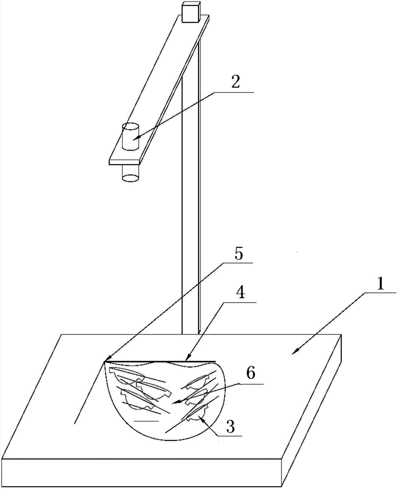
[0030] figure 1 It is a structural schematic diagram of the valve leaflet cutting device of the present invention; figure 2 It is a structural schematic diagram of the positioning unit of the present invention.

[0031] This embodiment discloses a valve leaflet cutting device, such as figure 1 As shown, it includes positioning unit, control unit and cutting unit.

[0032] Such as figure 2 As shown, the positioning unit includes a leaflet template 3, a light box 1 and an imaging device 2 placed above the light box; the leaflet template 3 is an opaque plastic plate that is different in color from the pericardial material 6 of the animal. The leaflet template 3 has the same shape as the leaflet of the valve to be cut. The leaflet template 3 is divided into two groups according to the model of the valve leaflet, and each group has three pieces. The imaging device is a conventional camera, which is used to record the position of the leaflet template; the light box is provide...

Embodiment 2

[0036] This embodiment discloses a valve leaflet cutting method, using the valve leaflet cutting device described in Embodiment 1, specifically including the following steps:

[0037](1) Use scissors to trim a corner and a side of the animal pericardium material, spread the animal pericardium material on the light box, make the corner coincide with the origin, and align one side with the X axis;

[0038] (2) Turn on the light box, the light emitted by the light box passes through the animal pericardium material, judge the thickness of the animal pericardium material and the texture direction of the tissue according to the intensity of the light passing through the animal pericardium material, and determine the leaflet according to the thickness and texture orientation of the animal pericardium material The appropriate cutting position, direction and model, and place the two valve leaflet templates at positions suitable for cutting valve leaflets;

[0039] (3) The camera equipm...


PUM


Abstract

The invention provides equipment and a method for cutting and selecting valves and valve leaflets. The equipment comprises a positioning unit, a control unit and a cutting unit, wherein the positioning unit comprises a valve leaflet template, a lamp box and a camera disposed above the lamp box, the color of the valve leaflet template is different from that of an animal pericardium material, the valve leaflet template and a valve and valve leaflet to be cut are identical in shape, the camera is used for recording positions of the valve leaflet template, the control unit is electrically connected with the camera and the cutting unit respectively and used for sending the positions, of the valve leaflet template, recorded by the camera to the cutting unit, and the cutting unit cuts the animal pericardium material according to the positions, of the valve leaflet template, sent by the control unit. The equipment for cutting and selecting valves and valve leaflets is simple in structure, the method for cutting and selecting valves and valve leaflets is scientific, various defects in existing manual cutting and selecting of the valves and the valve leaflets are overcome, and the valves and the valve leaflets obtained by the equipment and the method have the advantages of excellent quality and high rate of finished products.

Description

technical field [0001] The invention relates to medical device technology, in particular to a valve leaflet cutting device and cutting method. Background technique [0002] Bioprosthetic valve is a three-leaf valve without chord pull based on biological material (such as animal pericardial material) component used for the treatment of heart diseases. At present, there is no specific equipment for bioprosthetic valve leaflet cutting, and it is all done manually. The cutting personnel The cutting scheme and cutting model are determined according to the thickness and grain orientation of the animal pericardium material (such as bovine pericardium). [0003] The thickness and grain orientation of the animal pericardial material are two important parameters that determine the performance of the valve leaflets. However, because the grain orientation of the animal pericardial material is messy and complex, the operator can only determine the leaflet according to the general directi...

Claims


Application Information

Patent Timeline
IPC IPC(8): A61F2/24
Inventor 钟生平靳永富
Owner KINGSTRONBIOCHANGSHU CO LTD
Why Eureka
Try Eureka