
Piezoelectric array ultrasonic transducer

An ultrasonic transducer and piezoelectric technology, applied in the direction of fluid using vibration, can solve the problems of difficult packaging, narrow bandwidth, poor stability and comprehensive performance, and achieve good integrity, convenient packaging, and improved sensitivity. Effect

Inactive Publication Date: 2015-06-17
UNIV OF ELECTRONICS SCI & TECH OF CHINA
View PDF5 Cites 2 Cited by
  • Summary
  • Abstract
  • Description
  • Claims
  • Application Information

AI Technical Summary

Problems solved by technology

Since the array transducer adopts a common upper electrode setting, the upper electrode is integrated, and the wiring method in which the upper electrode and the lower electrode overlap in space, it is easy to generate parasitic capacitance. Therefore, the arrangement of the upper and lower electrodes of the array transducer It has a great impact on the sensitivity and performance of the device; the lead-out method of each lower electrode wire will seriously affect the safety of the device's packaging and use; in addition, each array element in the device works at the same operating frequency, not only its Narrow bandwidth and low operating frequency
Therefore, the array transducer has disadvantages such as low sensitivity, narrow bandwidth, poor stability and comprehensive performance, difficult packaging, and difficult industrial production.

Method used


Image

  • Piezoelectric array ultrasonic transducer
  • Piezoelectric array ultrasonic transducer
  • Piezoelectric array ultrasonic transducer

Examples


Embodiment Construction

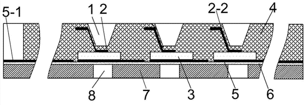
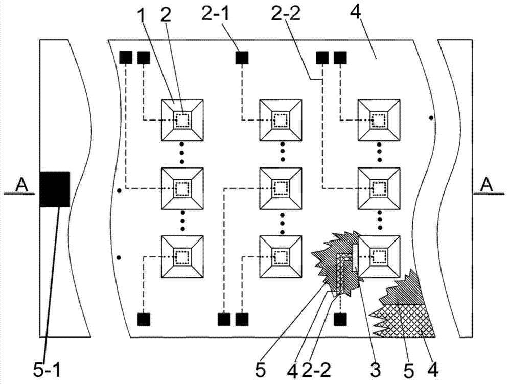
[0012] In this implementation mode, an ultrasonic transducer using AlN (aluminum nitride) piezoelectric thin film, the number of array elements is 2×2, two of which are 1.25MHz array elements and two of which are 2.9MHz array elements: the base 7 adopt (length×width×thickness) 10×10×0.25mm single crystal silicon, each vibrating cavity 8 set on it is (length×width×thick) 0.18×0.18×0.25mm, and the vibrating cavity 8 on it is (length×width×thickness) 0.18×0.18×0.25mm (2.9MHz array element) and 0.21×0.21×0.25mm (1.25MHz array element); the support layer 6 is made of silicon dioxide, its thickness is 350nm, and the length and width are equal The same as the substrate 7; the lower electrode 5 has the same horizontal length as the substrate, a longitudinal width of 7mm, and a thickness of 280nm, made of platinum-titanium alloy, magnetron sputtered on the silicon dioxide support layer 6, and the line corresponding to the lead-out line of the upper electrode The width of the shaped gap...


PUM


Abstract

The invention provides a piezoelectric array ultrasonic transducer, and belongs to the technical field of transducers and micro-processing. The piezoelectric array ultrasonic transducer comprises array (distributed) type upper electrodes, an integrated common lower electrode, piezoelectric films, insulation layers, array elements, a supporting layer, and monocrystalline silicon basements. The piezoelectric films are arranged between the upper electrodes and the lower electrode. The insulation layers are arranged among the upper electrode, the lower electrode and the piezoelectric films. The array elements arranged on the insulation layers comprises acoustic energy transmission and absorption cavities and vibration films at the bottoms of the array elements. The monocrystalline silicon basements are provided with vibration cavities. By the arrangement of adopting the common lower electrode and the array (distributed) type upper electrodes, same or different thicknesses are adopted in the vibration films at the bottoms of the array elements (the acoustic energy transmission and absorption cavities) and the piezoelectric films, so that the array elements can operate under either a same working frequency or different working frequencies, comprehensive performances of sensitivity and working bandwidth and stability of the comprehensive performances of the transducer can be improved effectively, and the piezoelectric array ultrasonic transducer has the advantages that integration is good, packaging is facilitated, industrial production is benefited and the like.

Description

technical field [0001] The invention belongs to the technical field of transducers and micromachining technology, in particular to a piezoelectric array ultrasonic transducer produced by micromachining technology, and the piezoelectric array ultrasonic transducer can be used as an audio frequency directional speaker on a mobile phone It can also be used as a new type of sensor in the field of medical electronics to detect ultrasound signals in ultrasound, photoacoustic and thermoacoustic imaging systems, and in smart homes for anti-theft systems. Background technique [0002] As a new sensor technology based on micromachining technology, the ultrasonic transducer in the present invention has attracted the attention of many foreign scientific research institutes, especially in the context of the rapid development of the information industry and the Internet of Things industry, it has also attracted attention in the commercial field. highly valued. Piezoelectric ultrasonic tr...

Claims


Application Information

Patent Timeline
Patent Type & Authority Patents(China)
IPC IPC(8): B06B1/06
Inventor 陈炳章蒋华北
Owner UNIV OF ELECTRONICS SCI & TECH OF CHINA
Learn More