Industrial continuous environmentally-friendly and energy-saving scrap tire thermal cracking equipment

A waste tire and energy-saving technology, which is applied in the field of industrial continuous environmental protection and energy-saving waste tire thermal cracking equipment, can solve the problems of high production cost, short service life and poor safety performance of thermal cracking equipment, and achieve good social and economic benefits. , long service life, good effect

Active Publication Date: 2013-08-14
SHANGQIU JINPENG IND CO LTD
2 Cites 24 Cited by

AI-Extracted Technical Summary

Problems solved by technology

[0003] In view of the above situation, in order to overcome the defects of the prior art, the object of the present invention is to provide an industrial continuous environmental protection and energy-saving w...

Method used

2, intermediate frequency power supply can fine-tune input power, realized the purpose of constant temperature heating, greatly improved the quality of obtained liquid oil and crude carbon black;
The present invention adopts magnetocaloric effect to heat cracking kettle, can effectively improve the safety of equipment, compared with prior art, the present invention has the following advantages:
The usage situation of the present invention is, power supply 28 is connected with power supply changeover switch 29 earlier through power lead, then is connected with intermediate frequency power supply 5,8a,8b,8c by lead, starts intermediate frequency power supply, common three-phase electric conversion Become a medium-frequency electricity with low-voltage high-current characteristics, and connect with the first electromagnetic coil 4 wound on the shell of the screw feeder and the second electromagnetic coil 7a, 7b, 7c wound on the body of the cracking kettle through wires, When the electromagnetic coil passes through the medium-frequency...

Abstract

The invention relates to industrial continuous environmentally-friendly and energy-saving scrap tire thermal cracking equipment which is capable of effectively solving the problems of bad safety and short service life of scrap tire thermal cracking equipment. The technical scheme is as follows: the scrap tire thermal cracking equipment comprises conveyors, a screw feeder, condensers, an auger machine, a magnetic separator, a circulating pump and a gas turbine generator, wherein the discharge end of a first conveyor is arranged above the feed opening of a second conveyor, the discharge end of the second conveyor is arranged above the feed opening of the screw feeder, the discharge end of the screw feeder is connected with the feed end of a cracking kettle, the discharge end of the cracking kettle is connected with a gas inlet of a reaction tower through an exhaust cylinder, the exhaust end of the reaction tower is connected with an oil storage tank through a first condenser and a second condenser, and the oil storage tank is sequentially communicated with a third condenser, a non-condensable gas washing tank, an alkali liquor storage tank, a liquid removing tank, a buffering tank, a vacuum pump, a cleaning tank, a compressor, a gas storage tank and a gas decompression tank to form a non-condensable combustible gas extracting system. The industrial continuous environmentally-friendly and energy-saving scrap tire thermal cracking equipment provided by the invention is safe, reliable, long in service life and good in effect.

Application Domain

Technology Topic

Image

  • Industrial continuous environmentally-friendly and energy-saving scrap tire thermal cracking equipment

Examples

  • Experimental program(1)

Example Embodiment

[0007] The specific embodiments of the present invention will be further described in detail below with reference to the accompanying drawings.
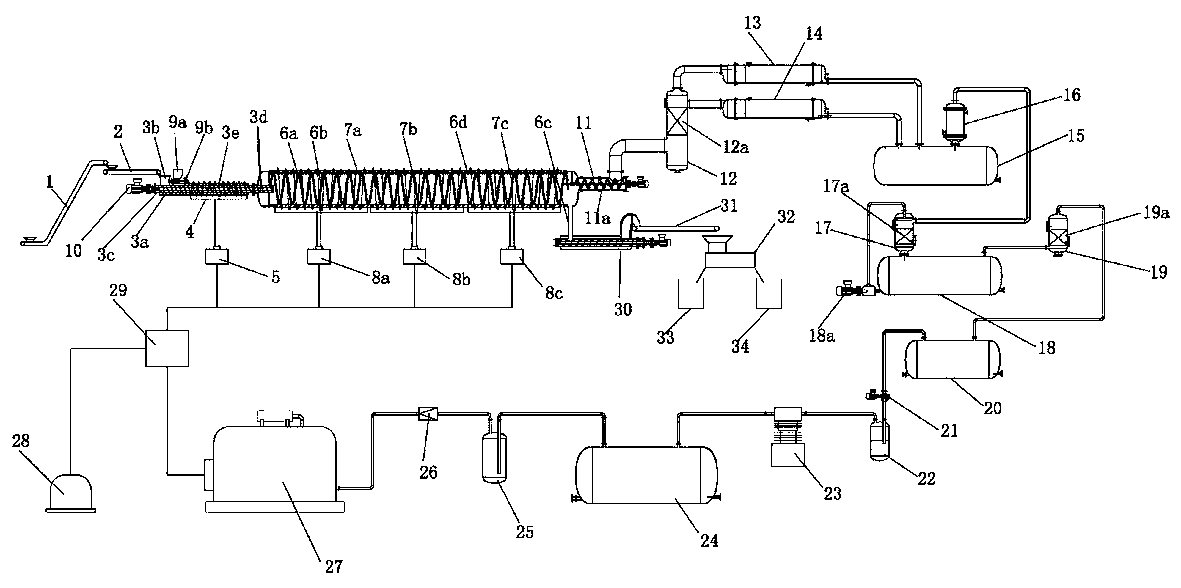
[0008] Depend on figure 1 Given, the present invention includes a conveyor, a screw feeder, a condenser, an auger, a magnetic separator, a circulating pump and a gas-fired generator, and the first conveyor 1 is inclined upward and placed on the second for material weighing. On one side of the conveyor 2, the discharge end of the first conveyor 1 for material lifting is placed above the feed port of the second conveyor 2, and the discharge end of the second conveyor 2 is placed at the inlet of the screw feeder. Above the material port 3b, the discharge end of the screw feeder is connected with the feed end of the cracking kettle, and the discharge end of the cracking kettle is connected with the air inlet of the reaction tower 12 through the gas outlet cylinder 11, and the gas outlet ends of the reaction tower 12 are respectively used. The first condenser 13 and the second condenser 14 for condensing oil and gas are connected with the oil storage tank 15, and the oil storage tank 15 is connected with the third condenser 16 for re-condensing oil and gas, the washing tank 17 for non-condensable gas, and the lye storage tank. The tank 18, the liquid removal tank 19, the buffer tank 20, the vacuum pump 21, the cleaning tank 22, the compressor 23, the gas storage tank 24, and the gas decompression tank 25 are connected in sequence to form a non-condensable combustible gas extraction system. The gas decompression tank The gas outlet of 25 is connected with the gas generator 27 through the flame arrester 26, the gas generator 27 is connected with the power transfer switch 29 through the wire, and the power transfer switch 29 is connected with the intermediate frequency power supply 5, 8a, 8b, 8c in parallel with the coils installed in the spiral respectively. The first electromagnetic coil 4 on the shell of the feeder and the second electromagnetic coils 7a, 7b, 7c wound around the body of the cracking kettle are connected to each other, start the intermediate frequency power supply, and convert ordinary three-phase electricity into low-voltage and high-current characteristics. Intermediate frequency electricity, when the electromagnetic coil passes through the intermediate frequency electricity with the characteristics of low voltage and high current, a strong magnetic field is generated, which directly acts on the kettle body 6d of the cracking kettle and the shell 3c of the screw feeder for preheating. Under the hood, the body of the pyrolysis kettle and the shell of the screw feeder heat up by themselves, and the temperature rises steadily. The temperature of the pyrolysis kettle rises steadily without contacting an open flame, which greatly improves the service life of the equipment; the power source 28 is connected to the power switch 29, The slag drop port 6c of the cracking kettle is connected to the feed end of the auger 30, and the discharge end of the auger 30 is connected to the feed end of the magnetic separator 32 through the third conveyor 31, and the discharge end of the magnetic separator 32 is connected. The ports are respectively connected to the inlets of the steel wire storage box 34 and the carbon black storage box 33, and the coarse carbon black and steel wires obtained by endothermic cracking of waste tires in the cracking kettle enter into the auger 30 through the slag drop port 6c, and from the auger The material coming out is sent to the magnetic separator 32 by the third conveyor 31, and the steel wire and carbon black are separated by magnetic separation, and are respectively stored in the steel wire storage box 34 and the carbon black storage box 33, so as to effectively achieve the separation of the steel wire and the carbon black. , to realize the industrial continuous production of waste tire recycling and reuse.
[0009] In order to ensure the use effect, the screw feeder includes a casing 3c, a motor 10 and a conveying screw. The conveying screw is composed of a rotating shaft 3d and a screw blade 3e mounted on the rotating shaft. Both ends of the rotating shaft are horizontally installed in the casing. , the motor 10 is connected to one end of the rotating shaft extending out of the casing, the casing 3c is covered with a first thermal insulation cotton 3a, the first electromagnetic coil 4 is wound on the first thermal insulation cotton, and the feeding end of the screw feeder is on the casing The upper part is sequentially equipped with a cracking agent storage bin 9a and a cracking agent conveyor 9b connected with the cracking agent storage bin to form a cracking agent adding system;
[0010] The described cracking still includes a still body 6d and a rotating plate 6b, the rotating plate 6b is horizontally installed in the still body 6d, and one end of the rotating plate is connected with one end of the rotating shaft 3d extending into the still body, forming a rotating conveying structure, and the Covered with a second thermal insulation cotton 6a, and the second electromagnetic coils 7a, 7b, 7c are wound on the second thermal insulation cotton in turn;
[0011] The air outlet 11 is equipped with an anti-blocking auger 11a;
[0012] Described reaction tower 12 is equipped with stainless steel Pall ring packing 12a for molecular reorganization;
[0013] The liquid outlet at the lower part of the lye storage tank 18 is connected with the liquid inlet of the circulating pump 18a, and the liquid outlet of the circulating pump 18a is connected with the inlet on the upper part of the washing tank 17 to form a lye circulation system;
[0014] The washing tank 17 and the liquid removal tank 19 are respectively equipped with stainless steel Pall ring packings 17a and 19a.
[0015] The application of the present invention is that the power supply 28 is first connected to the power conversion switch 29 through the power supply wire, and then connected to the intermediate frequency power supply 5, 8a, 8b, 8c through the wire, and the intermediate frequency power supply is activated to convert the ordinary three-phase power into low-voltage power. The medium-frequency electricity with large current characteristics is connected with the first electromagnetic coil 4 wound on the shell of the screw feeder, and the second electromagnetic coil 7a, 7b, 7c wound on the cracking kettle body through the wire, and the electromagnetic coil Through the medium frequency electricity with the characteristics of low voltage and high current, a strong magnetic field is generated to directly act on the kettle body of the cracking kettle and the shell of the screw feeder for preheating. Under the action of the magnetocaloric effect, the cracking kettle and the screw feed The temperature of the pyrolysis kettle rises steadily without contacting the open flame, which ensures that the oxidation of the kettle body is small, and the service life of the equipment is greatly improved; the intermediate frequency power supply can fine-tune the input power power, realize the purpose of constant temperature heating, and greatly improve the obtained The quality of liquid oil and crude carbon black; at the same time, the intermediate frequency power supply can be cut off in an instant, which greatly improves the safety performance of the equipment during operation; when the temperature in the cracking kettle reaches about 350 ℃, and the temperature of the screw feeder reaches about 250 ℃, the can start feeding;
[0016] The crushed and cleaned granular waste tires are sent to the second conveyor 2 through the first conveyor 1, and then enter the cracking kettle through the screw feeder. The heat makes its own temperature reach about 120 °C, and the waste heat dehydration process is completed. In this process, according to the amount of raw materials obtained by the second conveyor 2, the cracking agent adding system composed of the cracking agent storage bin 9a and the cracking agent conveyor 9b The weight ratio of the catalyst is added. For example, aluminum oxide is added to the waste heat screw feeder 3;
[0017] Then the waste tires enter the pyrolysis kettle, and the waste tires move forward slowly under the impetus of the rotating plate 6b in the kettle body. During the process of moving forward, the waste tires absorb heat and undergo thermal cracking, cracking a large amount of oil and gas and coarse carbon black. The steel wire in the waste tire is separated; when the pressure in the cracking kettle reaches about 100Pa at this time, turn on the vacuum pump 21, adjust the speed of the vacuum pump motor, so that the pressure in the cracking kettle is kept in the range of -20Pa-50Pa, when the vacuum pump 21 is turned on At the same time, the gas generator 27 should be started together. After the gas generator works for about half an hour, the external power supply 28 should be cut off, and the electric energy generated by the gas generator set 27 should be connected through the power transfer switch 29 . The electric power required for the subsequent production process is provided by the non-condensable combustible gas generated in the system through the electric power generated by the gas generator set 27 .
[0018] The macromolecular oil and gas cracked from the waste tires in the cracking kettle is decomposed and recombined into small molecular oil and gas under the action of the stainless steel Pall ring packing 12a in the reaction tower 12, and passed through the first condenser 13 and the second condenser 14. , condensed into liquid oil, which flows into the oil storage tank 15, and part of the uncondensed small molecule oil and gas and the non-condensable combustible gas at normal temperature and pressure are secondary cooled by the third condenser 16 connected to the top of the oil storage tank 15, Part of the uncondensed small molecule oil and gas is condensed into liquid oil, which flows into the oil storage tank 15 , and only the remaining non-condensable combustible gas at normal temperature and pressure enters the washing tank 17 .
[0019] The non-condensable combustible gas enters the washing tank 17 and mixes with the lye pumped by the circulating pump 18a. At this time, the alkaline substance in the lye solution and the acid substance in the non-condensable combustible gas undergo an acid-base neutralization reaction, so as to remove the non-condensable combustible gas. The purpose of acid substances in condensed flammable gases. After the non-condensable combustible gas is neutralized by acid and alkali, the residual lye in the non-condensable combustible gas is removed by the stainless steel Pall ring packing 19a in the liquid removal tank 19, stored in the buffer tank 20, and pumped through the vacuum pump 21. In the cleaning tank 22, it is compressed and stored in the storage tank 24 by the compressor 23, and finally enters the gas generator 27 through the flame arrester 26, and is burned to generate electricity.
[0020] The coarse carbon black and steel wire from the waste tire endothermic cracking in the cracking kettle enter the auger 30 through the slag drop port 6c, and the material from the auger is sent to the magnetic separator 32 through the third conveyor 31 The steel wire and carbon black are separated by magnetic separation and stored in the steel wire storage tank 34 and the carbon black storage tank 33 respectively.
[0021] The invention adopts the magnetocaloric effect to heat the cracking kettle, which can effectively improve the safety of the equipment. Compared with the prior art, the invention has the following advantages:
[0022] 1. During the overall heating process, the cracking kettle does not touch the open flame, which ensures that the oxidation of the cracking kettle is small and greatly improves the service life of the equipment;
[0023] 2. The intermediate frequency power supply can fine-tune the input power, realize the purpose of constant temperature heating, and greatly improve the quality of the obtained liquid oil and crude carbon black;
[0024] 3. The industrial continuous production is realized, the production cost is greatly reduced, and the working environment and labor intensity of the workers are improved;
[0025] 4. The intermediate frequency power supply can be cut off in an instant, which greatly improves the safety performance of the equipment during operation. It is an innovation in the waste tire cracking equipment and has good economic and social benefits.

PUM

no PUM

Description & Claims & Application Information

We can also present the details of the Description, Claims and Application information to help users get a comprehensive understanding of the technical details of the patent, such as background art, summary of invention, brief description of drawings, description of embodiments, and other original content. On the other hand, users can also determine the specific scope of protection of the technology through the list of claims; as well as understand the changes in the life cycle of the technology with the presentation of the patent timeline. Login to view more.

Similar technology patents

Classification and recommendation of technical efficacy words

  • Novel structure
  • Simple and reasonable

Digital controlled temp. regulating automatic water tap

InactiveCN101000111ANovel structureRealize the automation of water temperature adjustmentOperating means/releasing devices for valvesMultiple way valvesAutomatic faucetElectricity
Owner:宁波意耐特阀门有限公司

Safety intersection

Owner:HENAN UNIV OF CHINESE MEDICINE

Ratchet type anti-falling device

Owner:武汉天蝎建筑装备有限公司

Hidden type fine mist nozzle

Owner:HENAN HIGH POWER SPECIAL ELECTROMECHANICAL MFG
Why Eureka
Try Eureka