Countercurrent high-pressure-injection emulsion breaker filling device

A high-pressure injection and filling device technology, applied in the direction of chemical dehydration/demulsification, etc., can solve the problems of affecting the demulsification effect, uneconomical, inapplicability, etc., and achieves improved demulsification effect, convenient operation and reasonable design. Effect

Inactive Publication Date: 2013-08-14
梁光川 +2
View PDF3 Cites 6 Cited by
  • Summary
  • Abstract
  • Description
  • Claims
  • Application Information

AI Technical Summary

Problems solved by technology

Mainly by increasing the mixing distance to improve the mixing effect, oil samples with high viscosity and high density heavy oil are mostly distributed in laminar flow in the pipeline, and the mixing effect of the demulsifier and emulsion added in this way is not ideal
[0006] (2) Add demulsifier before lifting the pump. This method mainly promotes the mixing of demulsifier and emulsion through the high-speed shear of the pump. Since the demulsifier injected in the downstream way before the pump is mainly distributed in the filling position of the pipeline On one side, even with the shear of the pump, it is difficult to ensure that it is evenly mixed with the emulsion
At the same time, demulsifiers are generally high molecular polymers, with complex branch structures and many branch chains. Excessive pump shear rate may cause da

Method used


Image

  • Countercurrent high-pressure-injection emulsion breaker filling device
  • Countercurrent high-pressure-injection emulsion breaker filling device
  • Countercurrent high-pressure-injection emulsion breaker filling device

Examples


Embodiment Construction

[0021] Below in conjunction with specific embodiment, further illustrate the present invention.

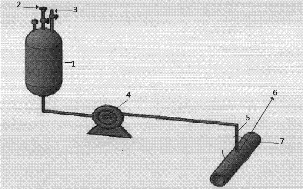
[0022] As can be seen from the figure, a countercurrent high-pressure injection demulsifier filling device, a storage tank (1), a feed port (2), an air outlet (3), a metering pump (4) and a filling pipe (5) and main pipe (7),

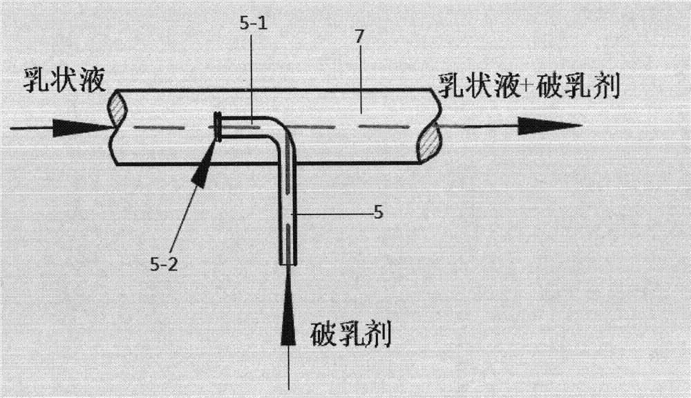
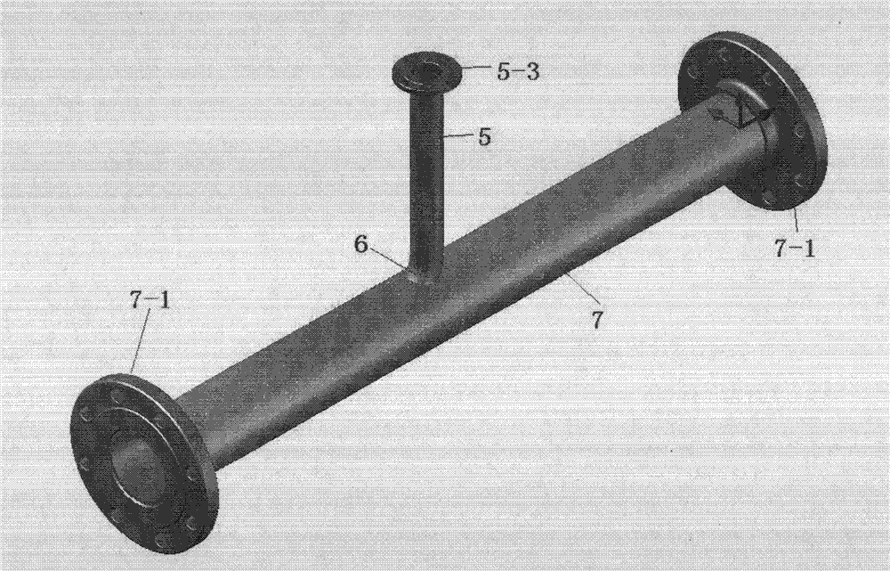
[0023] The feed opening (2) and the air outlet (3) are located on the top of the storage tank (1), the storage tank (1) is used to store the demulsifier, and the wall of the main pipeline (7) has a Injection hole (6), one end of the filling pipe (5) is connected to the bottom of the storage tank (1), and the other end passes through the filling hole (6) and enters the inside of the main pipeline (7), and the filling pipe (5) ) enters the inside of the main pipeline (7) to form a bent portion (5-1), the central axis of the bent portion (5-1) coincides with the central axis of the main pipeline (7), and the demulsifier is injected by The pipe (5) flows into...


PUM


Abstract

The invention relates to a countercurrent high-pressure-injection emulsion breaker filling device. The countercurrent high-pressure-injection emulsion breaker filling device comprises a storage tank (1), a feeding port (2), an air outlet hole (3), a measuring pump (4), a filling pipe (5) and a main pipeline (7). The countercurrent high-pressure-injection emulsion breaker filling device is simple in structure, reasonable in design and convenient to operate. When an emulsion breaker is filled in a countercurrent high-pressure injection way, the defects that the emulsion breaking time is short and the mixing is non-uniform can be overcome, and the emulsion breaking effect can be improved; and drastic turbulent flow can ensure that the emulsion breaker is uniformly mixed with crude oil emulsion, so that the emulsion breaker can rapidly reach an oil-water interface, and the stability of the emulsion can be broken.

Description

technical field [0001] The invention relates to a countercurrent high-pressure injection demulsifier filling device. Background technique [0002] At present, the commonly used demulsifier filling methods in oilfields include: drip injection process, injection injection process, etc. The filling point of these traditional filling processes is mostly set at the tee position of the pipeline, and some are even injected directly from the pressure gauge interface. The common feature of these injection methods is that the demulsifier injected into the pipeline flows along with the crude oil emulsion. At present, most domestic crude oil has the characteristics of high viscosity and high density, and the flow in the pipeline is laminar flow, which causes the injection to break. It is very difficult to mix the emulsion and the crude oil emulsion evenly. If there is no vigorous stirring or pump and other equipment shearing process after the filling process, the demulsifier is difficul...

Claims


Application Information

Patent Timeline
IPC IPC(8): C10G33/04
Inventor 梁光川彭星煜张兵强
Owner 梁光川
Why Eureka
Try Eureka