Direct current micro grid topology design method based on DC-DC (Direct Current-Direct Current) sectionalizers

A technology of DC microgrid and design method, applied in the field of microgrid, can solve the problems of questioned reliability, equipment damage and switch, complicated control, etc., to achieve the effect of improving system reliability, reducing the range of power outages, and responding quickly.

Inactive Publication Date: 2013-08-14
NORTH CHINA ELECTRIC POWER UNIV (BAODING)
View PDF6 Cites 19 Cited by
  • Summary
  • Abstract
  • Description
  • Claims
  • Application Information

AI Technical Summary

Problems solved by technology

However, the DC system requires a large-capacity capacitor to eliminate the voltage ripple. When a short-circuit fault occurs, the transient current caused by the instantaneous discharge of the capacitor may cause damage to the equipment or misoperation of the switch, resulting in the failure of the selective protection function and the power outage of a large number of loads and protection equipment. Deterioration of inter-coordination ability and other issues
At the same time, DC high-power solid-state circuit breakers are expensive, complicated to control, and questionable in reliability, so it is difficult to be widely used in DC microgrids

Method used


Image

  • Direct current micro grid topology design method based on DC-DC (Direct Current-Direct Current) sectionalizers
  • Direct current micro grid topology design method based on DC-DC (Direct Current-Direct Current) sectionalizers

Examples


Embodiment Construction

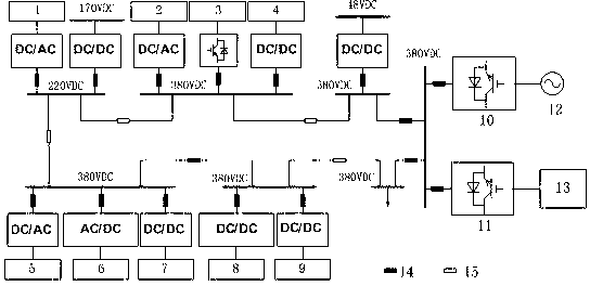
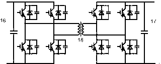
[0009] The principle circuit diagram of the DC microgrid topology design method proposed by the present invention is as attached figure 1 As shown, the grid structure of the DC microgrid adopts a ring structure, and the ring bus is divided into multiple sections and multiple voltage levels. Photovoltaic power generation (8) and DC loads (4), (7), (9) are connected to the bus through DC / DC converters and circuit breakers (14), wind power generation (3), micro gas turbines (6) and AC loads (1), (3), (5) are connected to the busbar through AC / DC converter and circuit breaker (14). The DC micro grid as a whole is connected to the AC large grid (12) and the energy storage device (13) through VSCs (10) and (11) capable of bidirectional power flow. Each segment of the bus is connected by a circuit breaker (14) or a DC / DC sectionalizer (15), forming a multi-divided and multi-connected power supply pattern. as attached figure 2 As shown, the connection between the DC bus (16) and t...


PUM


Abstract

The invention provides a direct current micro grid topology design method based on DC-DC (Direct Current-Direct Current) sectionalizers and belongs to the technical field of micro grid. In an annular direct current micro grid topology, a plurality of direct current micro grid sectionalizers based on high frequency isolation DC/DC conversion (short for DC-DC sectionalizers) are arranged for replacing solid circuit breakers. A direct current micro grid wire frame is of an annular structure, and an annular busbar is divided into a plurality of segments and a plurality of voltage levels. Adjacent busbar segments are connected through the DC-DC sectionalizers or circuit breakers so as to form a power supply layout with multiple segmentations and multiple connections. The DC-DC sectionalizers are of a dual full bridge topology structure, and are subjected to alternating current coupling through high-frequency transformers. The direct current micro grid topology design method has the advantages that on the aspects such as electric isolation, power flow control and connection among busbars with different voltage levels, the method has obvious superiority, the response speed is rapid and the sensitivity is high. When a direct current busbar or device has a fault, the DC-DC sectionalizers are not affected by capacitance instantaneous discharge, the faulted busbar is isolated, the power failure range is reduced as far as possible, and the reliability of the system is improved.

Description

technical field [0001] The invention relates to the technical field of micro-grids, in particular to a DC-DC micro-grid topology design method based on a DC-DC segmenter, in which a plurality of high-frequency isolated DC-DC conversion devices are configured in a ring topology instead of a solid-state circuit breaker. Background technique [0002] As a form of microgrid that connects distributed power and the main grid, DC microgrid can efficiently play the value and benefits of distributed power, and effectively isolate intermittent power disturbances, power quality problems and various problems in the main grid. effect of a failure. Therefore, research institutions at home and abroad have successively carried out the research and engineering practice of DC microgrid related theories. However, the DC system requires a large-capacity capacitor to eliminate the voltage ripple. When a short-circuit fault occurs, the transient current caused by the instantaneous discharge of t...

Claims


Application Information

Patent Timeline
Patent Type & Authority Applications(China)
IPC IPC(8): H02J3/36H02M3/315
CPCY02E60/60
Inventor 尹忠东姜喆王淼刘人玮王书瑶王帅田雨
Owner NORTH CHINA ELECTRIC POWER UNIV (BAODING)
Why Eureka
Try Eureka