
Switching method of position-sensor-free direct torque motor control system

A torque motor and control system technology, applied in control systems, electronic commutation motor control, electrical components, etc., can solve problems such as poor stability, impact, and inability to obtain accurate rotor positions

Inactive Publication Date: 2013-08-14
WUXI ECOVI TECH
View PDF7 Cites 14 Cited by
  • Summary
  • Abstract
  • Description
  • Claims
  • Application Information

AI Technical Summary

Problems solved by technology

However, since the back electromotive force of the motor at rest or at low speed is zero or very small, the accurate rotor position cannot be obtained, causing the motor to fail to start. Therefore, other methods need to be set up to realize the start of the motor. The currently disclosed methods generally use open loop Controlled start, and then switch to closed-loop control operation, but there is an impact when switching, and the stability is poor

Method used


Image

  • Switching method of position-sensor-free direct torque motor control system
  • Switching method of position-sensor-free direct torque motor control system
  • Switching method of position-sensor-free direct torque motor control system

Examples


Embodiment 1

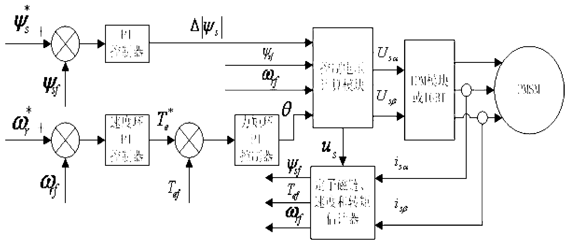
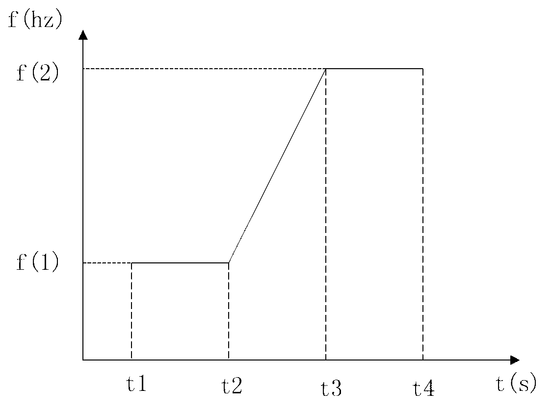
[0056] Embodiment 1, see figure 1 As shown, a switching method of a position sensorless direct torque motor control system, wherein: a non-disturbance switching section is added in the switching process between the open-loop control starting state and the closed-loop control running state, and the non-disturbance switching section refers to During the switching period t3-t4, the switching frequency f2 is maintained to obtain the estimated quantities of various parameters required for the closed-loop control operation of the motor, and to prepare for the motor from its open-loop control starting state to the closed-loop control running state. The estimated parameters are used as the corresponding control parameters of the closed-loop control operation of the motor to realize the undisturbed switching of the motor from the open-loop control starting state to the closed-loop control running state.

Embodiment 2

[0057] Embodiment 2, see figure 1 As shown, a switching method of a position sensorless direct torque motor control system, wherein: the estimated parameters of each parameter include stator flux linkage, electromagnetic torque and rotor speed; the corresponding control parameters of the closed-loop control operation of the motor Including the initial value of the stator flux linkage vector amplitude setting value, the initial value of the integral item of the speed loop and the initial value of the integral item of the torque loop, the rest are the same as the first embodiment.

Embodiment 3

[0058] Embodiment 3, as figure 1 As shown, a switching method of a position sensorless direct torque motor control system, wherein: the motor is a permanent magnet synchronous motor PMSM, and the specific steps of the non-disturbance switching section are:

[0059] (1) The non-disturbance switching section maintains the switching frequency f2 during the switching period t3-t4;

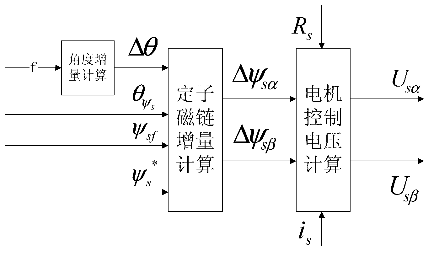
[0060] (2) According to the stator output voltage U s and the detected stator current i s Estimate stator flux linkage Estimate vector magnitude ψ sf and stator flux linkage to estimate the vector angle ;

[0061] (3) Estimation of vector angle based on stator flux linkage Estimated rotor speed estimate W rf , and estimate the vector magnitude ψ based on the stator flux linkage sf and stator current i s Estimated electromagnetic torque estimate T ef ;

[0062] (4) When switching, the estimated value of rotor speed W at the instant before switching rf Rotor feedback speed as motor closed lo...


PUM


Abstract

The invention relates to a switching method of a position-sensor-free direct torque motor control system, wherein a non-disturbance switching section is added in the switching process of the open loop control starting state and the closed loop control operation state, in the non-disturbance switching section, the switching frequency operation is maintained in the switching time period, each parameter estimation quantity required by the motor closed loop control operation is obtained, the preparation is made for the motor from the open loop control starting state to the closed loop control operation state, in addition, each parameter estimation quantity is used as corresponding control parameters of the motor closed loop control operation during the switching, the non-disturbance switching of the motor from the open loop control starting state to the closed loop control operation state is realized, and the switching moment control stability is effectively ensured.

Description

technical field [0001] The invention relates to a switching method of a position sensorless direct torque motor control system. Background technique [0002] Direct Torque Control (Direct Torque Control——DTC), some foreign original texts are also called Direct self-control——DSC, literally translated as direct self-control, which means that the torque is directly controlled as the controlled quantity, and its essence is Using the analysis method of space vector, the stator flux linkage and electromagnetic torque of the motor are directly controlled in the way of stator magnetic field orientation. This method does not require complex coordinates, but directly calculates the magnitude of the flux linkage and torque on the coordinates of the motor stator, and realizes PWM pulse width modulation and high dynamic performance of the system through direct tracking of flux linkage and torque. In the control process, a position sensor is required to detect the rotor magnetic pole pos...

Claims


Application Information

Patent Timeline
Patent Type & Authority Applications(China)
IPC IPC(8): H02P6/00
Inventor 何志明徐柳春陈俊黄雨
Owner WUXI ECOVI TECH
Learn More