
Plasma irradiation platform

A plasma and irradiation technology, applied in irradiation devices, nuclear engineering, etc., to achieve the effects of high experimental efficiency, simple operation, and low cost

Inactive Publication Date: 2013-08-21
DALIAN NATIONALITIES UNIVERSITY
View PDF6 Cites 7 Cited by
  • Summary
  • Abstract
  • Description
  • Claims
  • Application Information

AI Technical Summary

Problems solved by technology

So far, there have been few reports on the use of low-pressure low-temperature plasma to simulate irradiated fusion materials

Method used


Image

  • Plasma irradiation platform
  • Plasma irradiation platform

Examples


Embodiment 1

[0026] A plasma irradiation platform;

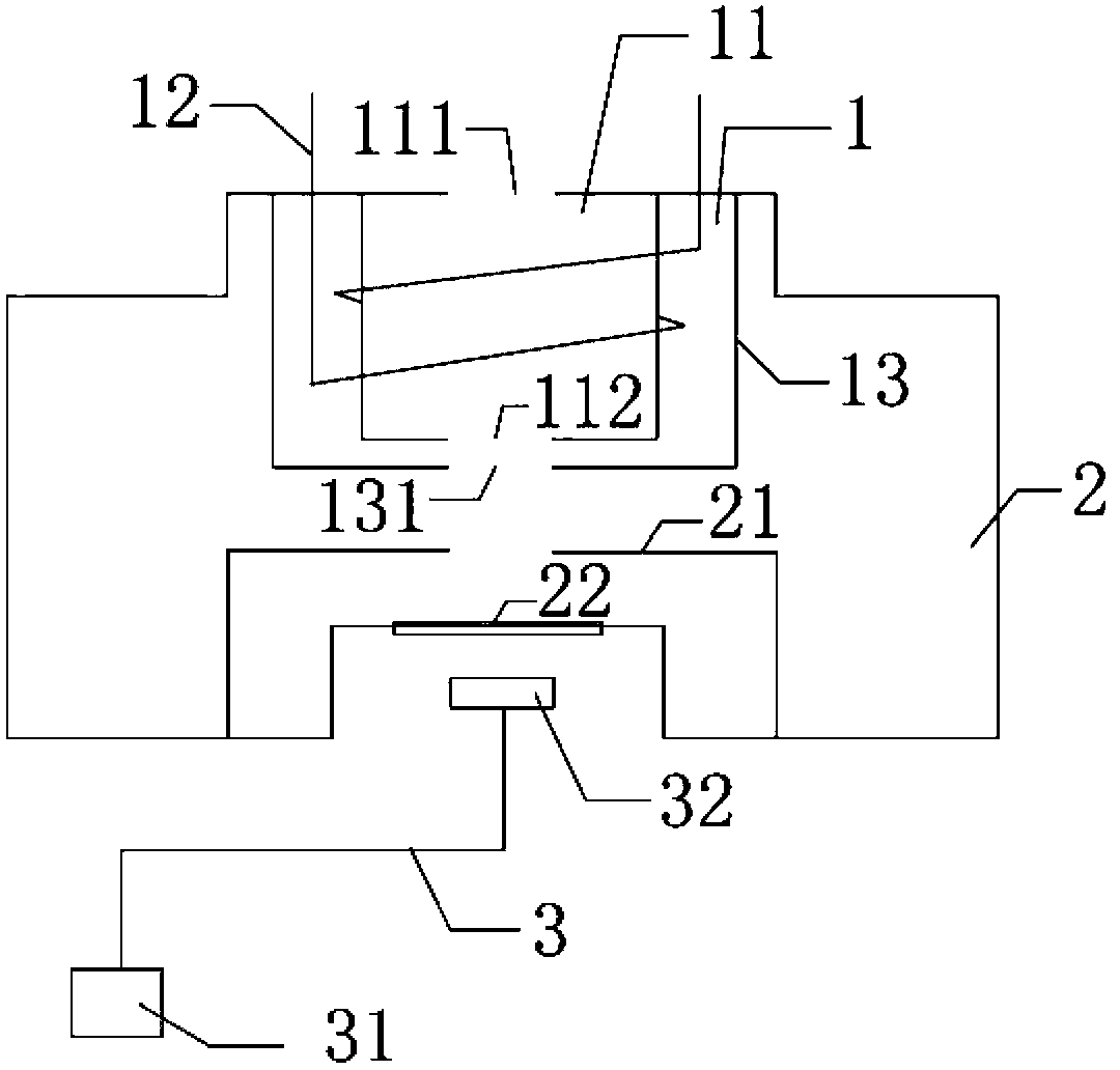
[0027] The plasma irradiation platform includes an ion source 1, a cavity 2 and a laser heating system 3, the ion source 1 is sealed in the cavity 2, the laser heating system 3 is outside the cavity 2, and the ion source 1 It includes a quartz tube 11, a copper tube 12 wound on the outer wall of the quartz tube, and a shield 13 for shielding radio frequency electric fields. The quartz tube 11 and the copper tube 12 wound on the outer wall of the quartz tube are placed in the shield 13. The upper end of the quartz tube 11 is provided with an air inlet 111 communicating with the outside of the cavity, the air inlet 111 is provided with a volume flowmeter for controlling the gas flow, the lower end of the quartz tube 11 is provided with an ion injection port 112, and the quartz tube 11 A thermocouple vacuum gauge for measuring pressure is installed inside, the two ends of the copper tube 12 are connected to the two ends of the radio frequen...


PUM


Abstract

The invention relates to a plasma irradiation platform, and belongs to the technical field of application of plasma. The plasma irradiation platform comprises an ion source, a cavity and a laser heating system, wherein the ion source is sealed inside the cavity, and the laser heating system is arranged outside the cavity. The ion source comprises a quartz tube, a copper tube and a shielding cover, wherein the copper tube is wound on the outer wall of the quartz tube, the shielding cover is used for shielding a radio frequency electric field, and the quartz tube and the copper tube wound on the outer wall of the quartz tube are arranged inside the shielding cover. An air inlet is arranged at the upper end of the quartz tube, an ion spraying port is arranged at the lower end of the quartz tube, two ends of the copper tube are connected with two ends of a radio frequency power supply outside the cavity, a through hole is formed at the bottom of the shielding cover, a sample platform arranged inside the cavity is located under the ion source, and a quartz window arranged under the sample platform is in seal connection with the cavity. The laser heating system comprises a combination type laser which is fixed under the quartz window. The plasma irradiation platform has the advantages of being simple in equipment, low in cost, short in experimental period, and high in experimental efficiency.

Description

technical field [0001] The invention relates to a plasma irradiation platform, which belongs to the field of plasma application technology. Background technique [0002] In recent decades, with the rapid development of human society, the demand for energy is also increasing, but the available energy is less and less. The realization of controllable nuclear fusion has become a research hotspot in the world today. Controllable nuclear fusion has Two major problems: the steady-state plasma problem and the key material problem of the reactor. At present, many research groups in the world are carrying out research work in this area, but there are few studies on the first wall material of low-temperature plasma simulation irradiation fusion reactor and the radiation damage mechanism of the first wall material. This type of device capable of simulating fusion reactor irradiation is relatively rare at home and abroad, and the purpose and construction methods of the devices are also...

Claims


Application Information

Patent Timeline
IPC IPC(8): G21K5/02
Inventor 刘东平杨德明范红玉
Owner DALIAN NATIONALITIES UNIVERSITY
Learn More