Piezoelectric cantilever beam generator for wind driven generator blade monitoring system

A technology for wind turbines and monitoring systems, applied in the directions of generators/motors, piezoelectric effect/electrostrictive or magnetostrictive motors, electrical components, etc., can solve the problem that micro-miniature power generation devices cannot meet the self-power supply requirements of monitoring systems , low power generation efficiency and other problems, to achieve the effect of novel structure, strong power generation capacity, effective speed and bandwidth

Inactive Publication Date: 2013-08-21
ZHEJIANG NORMAL UNIVERSITY
View PDF11 Cites 29 Cited by
  • Summary
  • Abstract
  • Description
  • Claims
  • Application Information

AI Technical Summary

Problems solved by technology

[0005] The invention provides a piezoelectric cantilever generator used in a wind turbine blade monitoring system to solve the problem that the current miniature power generation device cannot meet the self-power supply requirements of the monitoring system, and the cantilever-type rotary piezoelectric generator has no vibration and generates electricity. The problem of inefficiency

Method used


Image

  • Piezoelectric cantilever beam generator for wind driven generator blade monitoring system
  • Piezoelectric cantilever beam generator for wind driven generator blade monitoring system
  • Piezoelectric cantilever beam generator for wind driven generator blade monitoring system

Examples


Embodiment Construction

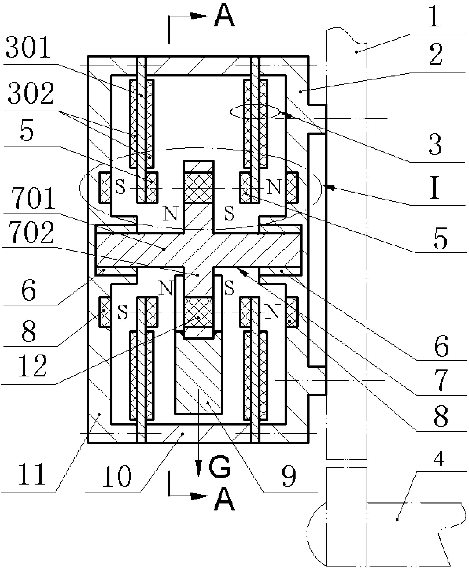
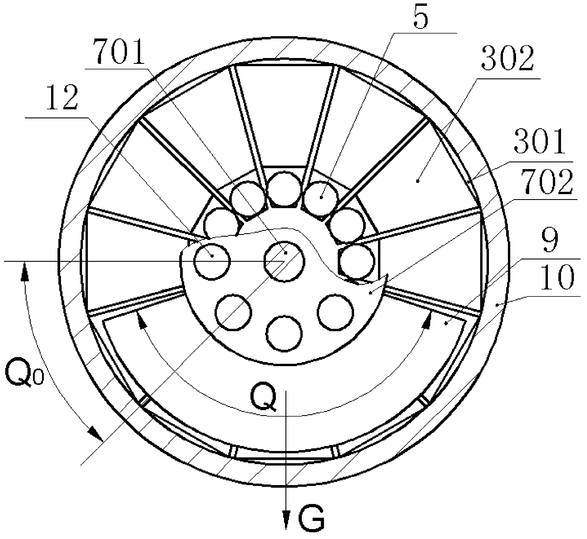
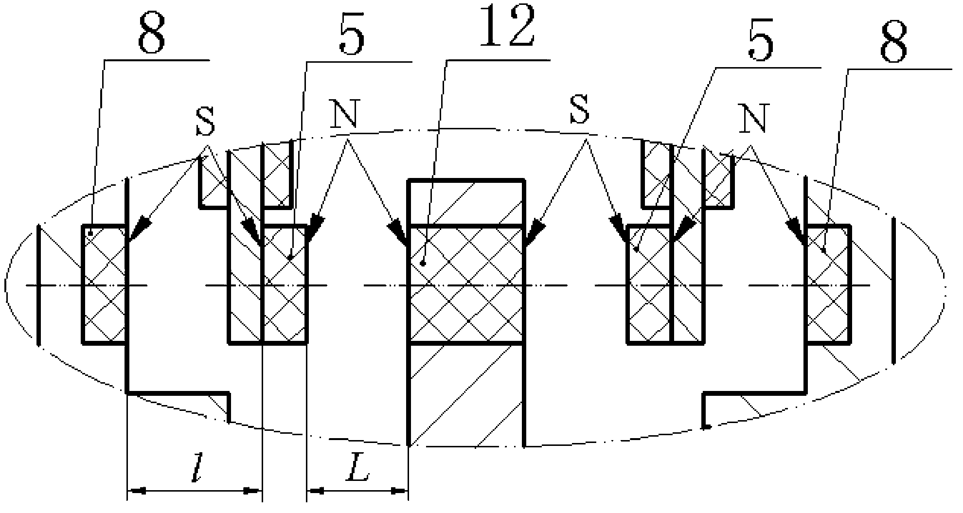
[0016] The left end cover 11 and the right end cover 2 are respectively installed on the two ends of the housing 10 by screws, and the inner side of the bottom of the left end cover 11 and the right end cover 2 are respectively inlaid with a first magnet 8 and a shaft sleeve 6; A metal substrate 301 is crimped between the right end cover 2 and the housing 10, the metal substrate 301 and the piezoelectric chips 302 bonded on both sides together form a fan-shaped cantilever beam piezoelectric vibrator 3, the piezoelectric The free end of the vibrator 3 is installed with a second magnet 5 through a screw, and the second magnet 5 coincides with the center line of the first magnet 8 installed on the inner side of the bottom of the left end cover 11 and the right end cover 2; In the hole of the sleeve 6 embedded in the bottom of the left end cover 11 and the right end cover 2, the rotating shaft 701 is hinged with the inner hole of the sleeve 6; the outer edge of the disc body 702 of...


PUM


Abstract

The invention relates to a piezoelectric cantilever beam generator for a wind driven generator blade monitoring system and belongs to the field of new energy resources and power technology. A left end cover and a right end cover are installed at two ends of a shell body through bolts. The bottom of the left end cover and the bottom of the right end cover are respectively provided with a first magnet and a shaft sleeve in an embedded mode. Piezoelectric vibrators are connected between the left end cover and the shell body and between the right end cover and the shell body in a pressed mode. A second magnet is installed at a free end of each piezoelectric vibrator. A rotary shaft of a driving disc is placed in the shaft sleeve which is embedded at the bottom of the left end cover and the shaft sleeve which is embedded at the bottom of the right end cover. A mass block is welded to the outer edge of a driving disc body and a third magnet is embedded in the outer edge driving disc body. The piezoelectric cantilever beam generator for the wind driven generator blade monitoring system has the advantages that relative rotation is generated between the magnet arranged on the driving disc and the magnets arranged on the piezoelectric vibrators, the piezoelectric vibrators are effectively driven, power is generated, and external fixed supporting is not required; the generator is an independent assembly, so that the structure of each blade does not need to be changed, and installation and maintenance are convenient; the generator is composed of the fan-shaped piezoelectric vibrators with the magnets with different masses, so that the piezoelectric cantilever beam generator for the wind driven generator blade monitoring system is high in reliability, strong in power generation capacity and wide in speed band.

Description

technical field [0001] The invention belongs to the technical field of new energy and power generation, and in particular relates to a piezoelectric cantilever generator used in a wind generator blade monitoring system. Background technique [0002] The blade is the key component of the wind turbine to receive wind energy and convert it into kinetic energy, which determines the overall reliability and service life of the generator. Wind turbine blades usually work in a harsh environment, and their structural scale, weight and working load are very large. In addition to being damaged by irresistible natural disasters such as lightning strikes and earthquakes, natural corrosion, wear and fatigue stress, etc. Leaf damage is also inevitable. Production practice shows that one-third of the accidents during the operation of wind turbines are caused by blade damage, so the health monitoring of wind turbine blades is imperative. With the increasing length of fan blades and the ove...

Claims


Application Information

Patent Timeline
Patent Type & Authority Applications(China)
IPC IPC(8): H02N2/18
Inventor 阚君武于丽王淑云徐海龙李胜杰程光明
Owner ZHEJIANG NORMAL UNIVERSITY
Why Eureka
Try Eureka