Continuous coal cutter

A technology for coal shearers and cutting motors, which is applied to cutting machinery, earthwork drilling, cutting machinery, etc. It can solve the problems of affecting the cutting efficiency of the whole machine, poor cooling effect of the whole machine, and affecting the operation of the working face. , to achieve the effect of improving cutting efficiency, improving operating efficiency and cooling effect

Active Publication Date: 2013-08-28
SANY HEAVY EQUIP
View PDF4 Cites 5 Cited by
  • Summary
  • Abstract
  • Description
  • Claims
  • Application Information

AI Technical Summary

Problems solved by technology

Because the fixed pick does not rely on active movement to cut the coal wall, when the hardness and toughness of the coal rock are relatively high, or when cutting coal or other minerals (such as potash ore, etc.) with undeveloped joints, this The cutting method is inefficient, which seriously affects the cutting efficiency of the whole machine;
[0004] 2. The cooling system of the existing continuous coal mining machine adopts an open cooling system, and the cooling effect is greatly affected by the ambient temperature of the working face. However, most roadways in my country's coal mines have poor ventilation conditions, and the ambient temperature of the working face is greater than 35°C. Therefore, The temperature rises rapidly during the operation of the equipment, resulting in poor cooling effect of the whole machine, increased failure rate, and affecting production efficiency. At the same time, cooling water is likely to cause water damage on the working surface, which seriously affects the operation of the working surface

Method used


Image

  • Continuous coal cutter
  • Continuous coal cutter
  • Continuous coal cutter

Examples


Embodiment Construction

[0033] It should be noted that, in the case of no conflict, the embodiments of the present invention and the features in the embodiments can be combined with each other. The present invention will be described in detail below with reference to the accompanying drawings and examples.

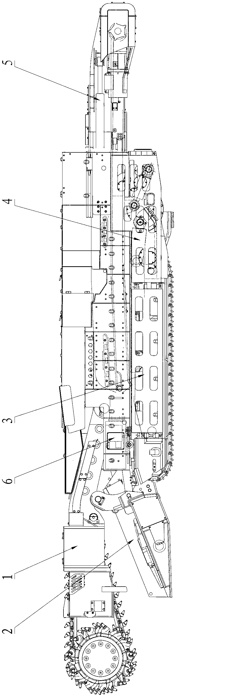
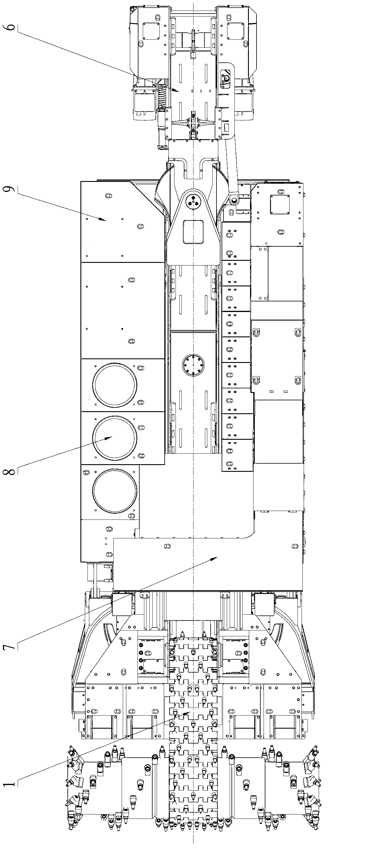
[0034] figure 1 with figure 2 It is the side structure view and the top view schematic diagram of the continuous coal miner described in this embodiment, combined with figure 1 , figure 2 It can be seen that the continuous coal miner described in this embodiment includes a cutting part 1, a shovel part 2, a walking part 3, a rear support part 4, a conveyor 5, a hydraulic system 6, a dust removal system 7, a closed cooling system 8 and an electrical system9.

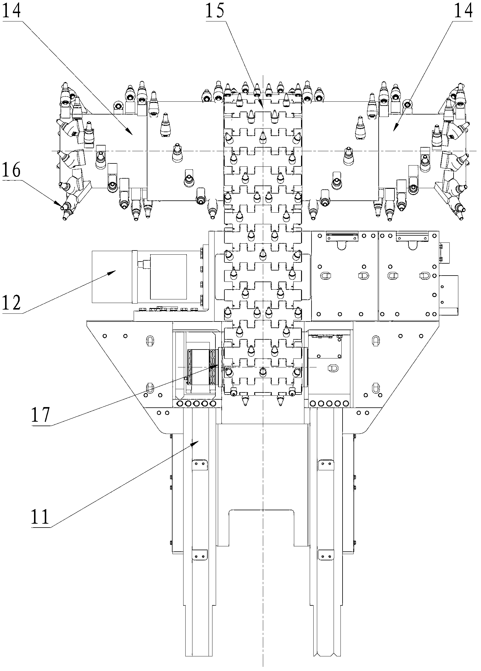
[0035] image 3 with Figure 4 They are respectively a top view schematic diagram and a bottom view angle schematic diagram of the cutting part 1 of the continuous coal miner described in this embodiment, combined with image 3 , ...


PUM


Abstract

The invention provides a continuous coal cutter, wherein a cutting part comprises a cutting motor arranged on a cutting arm, a cutting decelerator and a cutting roller arranged on an output end of the cutting decelerator, a cooling system of the continuous coal cutter is an enclosed cooling system, the cutting part further comprises a chain drive cutting device, the chain drive cutting device comprises a drive sprocket wheel set, a driven sprocket wheel set and a cutter chain, the drive sprocket wheel set is arranged on the output end of the cutting decelerator, and is coaxial with the cutting roller, the driven sprocket set is arranged on the cutting arm, the cutter chain, the drive sprocket wheel set and the driven sprocket wheel set are cooperated by chain drive, and picks are continuously distributed on an external surface of the cutter chain. The chain drive cutting device is arranged on the external side of the output end of the cutting decelerator of the continuous coal cutter. Accordingly, continuous active cutting mode can be implemented on whole cutting width, cutting efficiency can be greatly raised, the chain drive cutting device is suitable for conditions of joint non-development coal or other mineral matters, and an application range is increased.

Description

technical field [0001] The invention relates to the field of coal mine equipment, in particular to a continuous coal miner. Background technique [0002] Continuous coal miner equipment is a comprehensive coal mining equipment that integrates cutting, loading, walking, and spraying and dust suppression. It is mainly used for rapid tunneling of roadways, room-type or room-pillar coal mining, and corner coal mining. The current continuous miner mainly has the following two deficiencies: [0003] 1. The cutting part of the existing continuous coal miner is mainly arranged horizontally with two cutting motors, which are input into the cutting reducer at the same time, and the cutting rollers on both sides are respectively driven to work by the bidirectional input shaft of the cutting reducer. At the position of the output end of the cutting reducer, because the cutting reducer itself has a certain thickness, picks cannot be arranged outside the output end of the cutting reducer...

Claims


Application Information

Patent Timeline
Patent Type & Authority Applications(China)
IPC IPC(8): E21C25/52E21C31/02E21C35/00
Inventor 杨素玲李延富祁世栋刘文东刘兴利
Owner SANY HEAVY EQUIP
Why Eureka
Try Eureka