Piezoresistive-material-based resistivity imaging flexible pressure detection system and detection method

A resistivity imaging and detection system technology, applied in the direction of measurement force, measurement device, instrument, etc., can solve the problems of high measurement error, influence flexibility, increase the cost of pressure detection system, etc., to improve signal strength and measurement accuracy, good flexibility , the effect of low cost

Active Publication Date: 2013-08-28
INST OF ELECTRICAL ENG CHINESE ACAD OF SCI
View PDF5 Cites 32 Cited by
  • Summary
  • Abstract
  • Description
  • Claims
  • Application Information

AI Technical Summary

Problems solved by technology

On the one hand, this will increase the cost of the pressure detection system, on the other hand, it will also affect its flexibility, resulting in high measurement errors

Method used


Image

  • Piezoresistive-material-based resistivity imaging flexible pressure detection system and detection method
  • Piezoresistive-material-based resistivity imaging flexible pressure detection system and detection method

Examples


Embodiment Construction

[0025] The present invention will be further described below in conjunction with the accompanying drawings and specific embodiments.

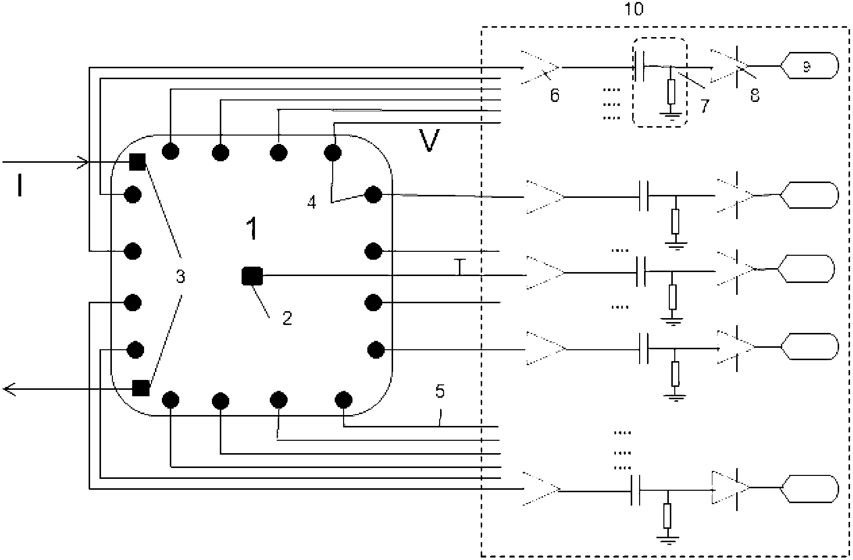
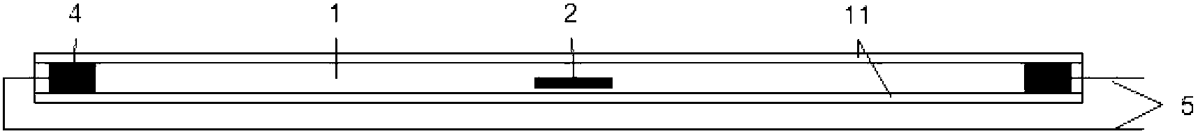
[0026] The flexible pressure detection system of the present invention mainly includes six parts: a pressure detection pad 1, a temperature sensor 2 buried inside the pressure detection pad, an injection electrode 3 connected to the edge of the pressure detection pad, and a plurality of uniform electrodes connected around the pressure detection pad. Distributed receiving electrodes 4 , wires 5 connected to the receiving electrodes 4 and the temperature sensor 2 , and a signal acquisition circuit 10 connected to the wires 5 . Its schematic diagram is as follows figure 1 shown.

[0027] The signal acquisition circuit 10 includes a plurality of shunts, and each shunt is connected to a receiving electrode 4 or a temperature sensor 2 through a wire 5, and the voltage signal detected by the receiving electrode 4 or the temperature signal detected by...


PUM

PropertyMeasurementUnit
diameteraaaaaaaaaa
diameteraaaaaaaaaa

Abstract

The invention discloses a piezoresistive-material-based resistivity imaging flexible pressure detection system, which comprises a pressure detection pad (1), a temperature sensor (2) buried in the pressure detection pad (1), injection electrodes (3) connected to the edge of the pressure detection pad (1), a plurality of uniformly distributed receiving electrodes (4) connected to the periphery of the pressure detection pad (1), wires (5) connected to the receiving electrodes (4) and the temperature sensor (2) and a signal acquisition circuit (10) connected with the wires (5), wherein the pressure detection pad (1) is made from a piezoresistive material; and when certain pressure is applied to the pressure detection pad, the resistivity of the material in the pressure detection pad can be changed. The injection electrodes connected to the pressure detection pad are used for injecting current into the pressure detection pad, the receiving electrodes arranged around the detection pad are used for receiving detected voltage signals, and an electrical impedance tomography principle is used for calculating resistivity distribution in the pressure detection pad to further invert the distribution of the pressure born by the pressure detection pad.

Description

technical field [0001] The invention relates to a pressure detection system and a detection method thereof, in particular to an electrical impedance imaging pressure detection system and a detection method thereof for medical rehabilitation aids. Background technique [0002] In rehabilitation engineering in the medical field, sometimes it is often necessary to measure the pressure distribution of a certain interface, such as the sitting aid system for children with cerebral palsy, joint rehabilitation aids, plantar pressure detection rehabilitation aids, etc. In addition, it is often used in daily life It involves the design of stress-bearing appliances such as car seats, wheelchairs, carpets, insoles, or joints of clothing, all of which require pressure analysis on a flexible interface, so that the use effects of these appliances or clothing can be optimized or improved. It can be seen from the above that the development of flexible pressure detection technology has very i...

Claims


Application Information

Patent Timeline
Patent Type & Authority Applications(China)
IPC IPC(8): G01L1/20
Inventor 李士强刘国强夏慧李艳红
Owner INST OF ELECTRICAL ENG CHINESE ACAD OF SCI
Why Eureka
Try Eureka