
Fully-automatic chemiluminescent immunoassay analyzer

An automatic chemistry and luminescent immunology technology, applied in the direction of analysis materials, instruments, etc., can solve the problems of low detection efficiency, impact on result consistency, and slow speed of the staff, so as to reduce cross-contamination of light between wells and ensure accuracy Sexuality, the effect of a short time interval

Active Publication Date: 2013-08-28
JIAXING QUEST LIFE SCI
View PDF6 Cites 21 Cited by
  • Summary
  • Abstract
  • Description
  • Claims
  • Application Information

AI Technical Summary

Problems solved by technology

However, the existing automatic chemiluminescent immunoassay analyzers on the market are all used to read the weak light energy emitted by 96 or 48-well microwell plates, and to measure the concentration of certain antibodies or antigens in patient serum samples. The so-called 96 or 48-well microplate means that the plate includes 96 or 48 cuvettes, and each patient serum sample to be tested is placed in a cuvette. When the number of samples to be tested is only a few or a dozen, the same A whole 96 or 48-well microplate needs to be used, thus causing a lot of waste; on the other hand, the existing fully automatic chemiluminescent immunoassay analyzers generally can only detect one microplate at a time, and the second microplate It needs to be put into the detector for detection after the first piece of detection is completed. Therefore, the detection speed is not fast and the detection efficiency of the staff is not high; It takes a long time, so it has a certain impact on the consistency of the results; the structure of the microplate cannot completely solve the problem of optical cross-contamination between wells

Method used


Image

  • Fully-automatic chemiluminescent immunoassay analyzer
  • Fully-automatic chemiluminescent immunoassay analyzer
  • Fully-automatic chemiluminescent immunoassay analyzer

Examples


Embodiment Construction

[0028] Below in conjunction with accompanying drawing and embodiment the present invention is described in further detail:

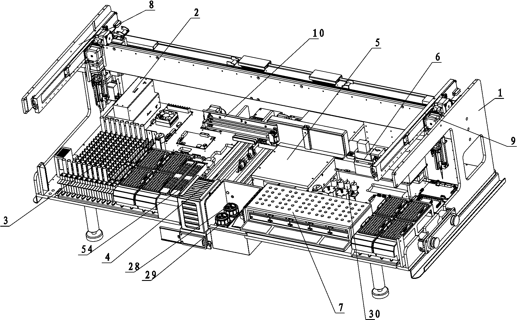
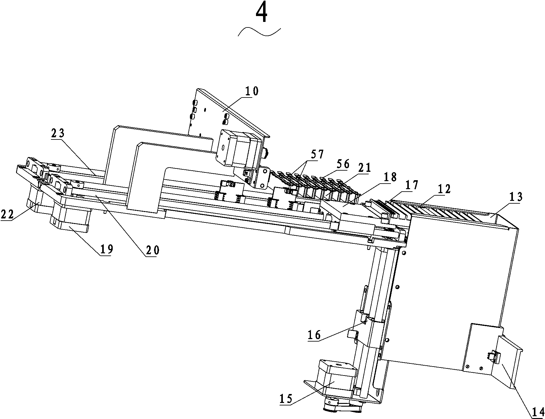
[0029] As an embodiment of the fully automatic chemiluminescence immunoassay analyzer of the present invention, such as figure 1 As shown, it includes a frame body 1 and a control system 2. The frame body 1 is provided with a sample area 3, a strip feeding system 4, an incubation area 5 and a strip detection system 6 in sequence from left to right. The bottom of the incubation area 5 is provided with a liquid circuit system, the bottom of the incubation area 5 is provided with a reagent area 7, the left side of the frame body 1 is provided with a sample arm 8, and the right side is provided with a reagent arm 9. 1, a first push rod arm 10 is arranged above the slat feeding system 4, a second push rod arm 11 is arranged inside the incubation area 5, the slat feeding system 4, the incubation area 5. The slat detection system 6 , the liquid circuit system,...


PUM


Abstract

The invention relates to a fully-automatic chemiluminescent immunoassay analyzer. The fully-automatic chemiluminescent immunoassay analyzer comprises a frame and a control system, a sample zone, a lath feeding system, an incubation zone and a lath detecting system are sequentially arranged on the frame from the left to the right, a fluid path system is arranged below or at the right side of the incubation zone, a reagent zone is arranged below the incubation zone and below or at the right side of the lath detecting system, a sample arm is arranged at the left side of the frame, a reagent arm is arranged at the right side of the frame, a first push rod arm is arranged above the lath feeding system on the frame, a second push rod arm is arranged in the incubation zone, and the lath feeding system, the incubation zone, the lath detecting system, the fluid path system, the sample arm, the reagent arm, the first push rod arm and the second push rod arm are respectively electrically connected with the control system. The fully-automatic chemiluminescent immunoassay analyzer has the advantages of simple structure, convenient operation, high automation degree, and supporting of the non-shutdown loading.

Description

technical field [0001] The invention relates to a fully automatic chemiluminescent immunoassay analyzer. Background technique [0002] The chemiluminescence immunoassay analyzer is a medical testing instrument for immune analysis of the human body by detecting the patient's serum. Add quantitative patient serum and horseradish peroxidase (HRP) to the white opaque microwell plate coated with antibodies on the solid phase, the combination of the molecules to be tested in the serum and horseradish peroxidase and the solid phase carrier The antibody on the antibody specifically binds, separates and washes the unreacted free components, and then adds a luminescent base solution, using the free energy released by the chemical reaction to excite the intermediate, returning from the ground state to the excited state, and the energy is released in the form of photons. However, the existing automatic chemiluminescent immunoassay analyzers on the market are all used to read the weak l...

Claims


Application Information

Patent Timeline
IPC IPC(8): G01N35/00
Inventor 周宋兵朱慧伟胡瑞倪剑锋
Owner JIAXING QUEST LIFE SCI
Features
  • Generate Ideas
  • Intellectual Property
  • Life Sciences
  • Materials
  • Tech Scout
  • Unparalleled Data Quality
  • Higher Quality Content
  • 60% Fewer Hallucinations
Learn More