
Air damper for vehicle

An air damping, automotive technology, applied in the direction of shock absorbers, shock absorbers, passenger space, etc., can solve the problems of increased defect rate, decreased productivity, increased air damper process and time, etc., to reduce the number of parts, prevent The effect of incorrect assembly and increased product competitiveness

Inactive Publication Date: 2013-08-28
NIFCO KOREA
View PDF7 Cites 2 Cited by
  • Summary
  • Abstract
  • Description
  • Claims
  • Application Information

AI Technical Summary

Problems solved by technology

[0006] Therefore, there is a problem that the steps and time for assembling the air damper increase and the productivity decreases.
[0007] In addition, there is a disadvantage that, in the process of forming a fixing hole at one end of the housing and connecting the cover with the corresponding fixing protrusion, the assembly may be assembled in a state where the connecting position is deviated, thereby increasing the defective rate.

Method used


Image

  • Air damper for vehicle
  • Air damper for vehicle
  • Air damper for vehicle

Examples


Embodiment Construction

[0024] Hereinafter, configuration and operation examples of the present invention for achieving the above objects will be described with reference to the drawings.

[0025] In the air damper for automobiles according to the present invention, the opening of the housing is integrally injection-molded with covers divided on both sides, and after assembling the piston, the covers are joined together to cover the opening and support the piston rod, thereby enabling Reduces parts count and shortens assembly and operating time.

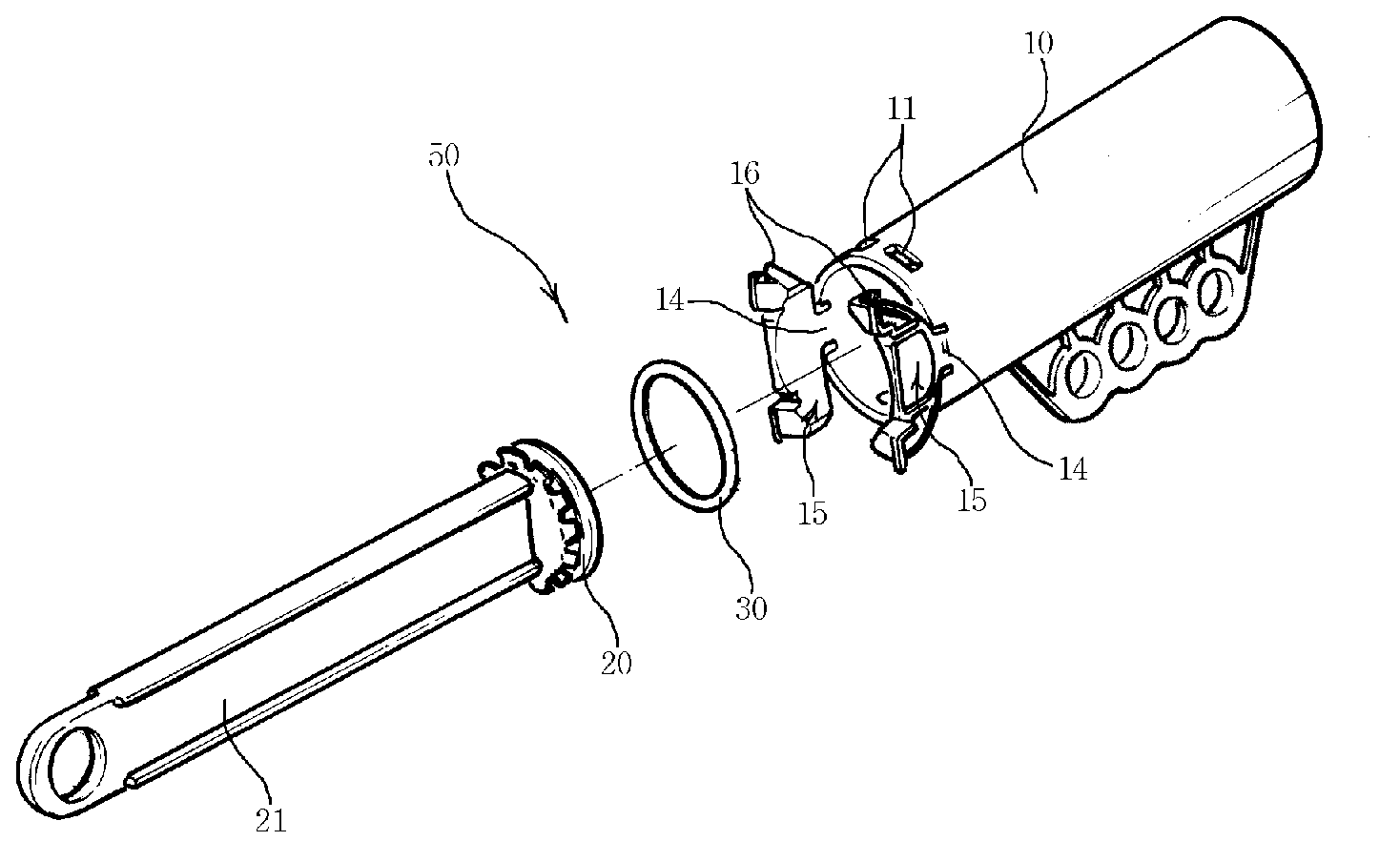
[0026] First, with Figure 3a and Figure 3b As a reference, the general direction reference used in this specification will be described. The piston 20 is inserted into the inside of the housing 10 to define an air chamber. Simultaneously, the piston rod 21 closes the opening.

[0027] At this time, an O-ring 30 is provided on the piston 20. The O-ring 30 is sleeved on the outer peripheral edge of the piston 20, and moves in contact with the inner diame...


PUM


Abstract

The present invention relates to an air damper for a vehicle, and more specifically, the invention enables: cover caps, which are divided into two sides, to be integrally injection-molded in an opening portion of a housing; and said cover caps to be coupled with each other to support a piston rod by shielding the opening portion after a piston has been assembled, thereby reducing the number of components and shortening assembling and operating time. The invention provides an air damper (50), in which: a piston (20) is inserted into a housing (10); and a cap (4) is inserted into a piston rod (21) such that the cap is penetrated therethrough whereby an opening portion of the housing (10) is assembled in a covered state, wherein cover caps (15), which are integrally injection-molded with a body on the opening portion of said housing (10), are divided into two sides in connection with the housing (10) by a hinge portion (14) such that the cover caps are assembled to enclose the inserted piston rod (21). Further, said cover caps (15) are inserted to surface contact with the inside diameter of the housing (10), and fixed protrusions (16) are formed on both ends of the cover caps (15) such that the fixed protrusions are inserted into fixed holes (11) equipped on the housing (10).; In addition, said cover caps (15) are divided into two sides and are assembled to be overlapped with each other on the front part of the opening portion, so that the fixed protrusions (16) and the fixed holes (11) mutually equipped on the front part of the body are coupled and assembled together, and then a protruded surface (17) is formed on the outer surface of the cover caps (15) while a position-fixing groove (12) is formed in the opening portion of the housing (10), whereby the protruded surface (17) is inserted and assembled into the position-fixing groove (12).

Description

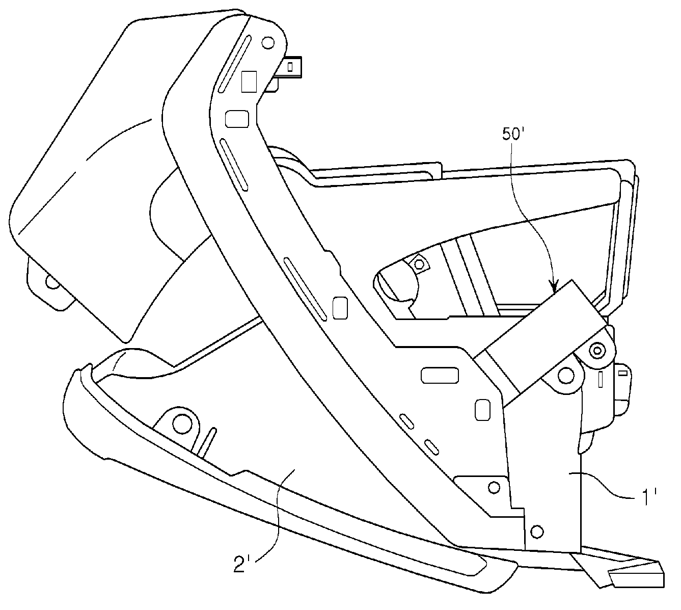
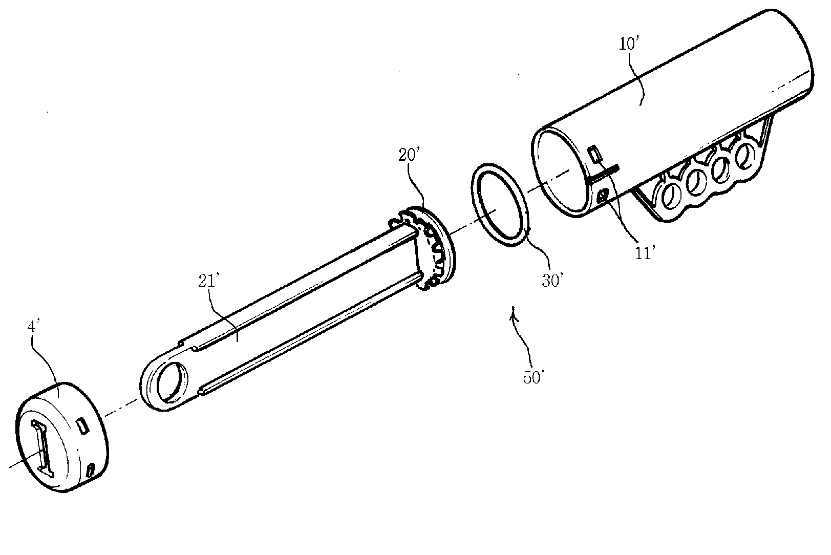
technical field [0001] The present invention relates to an air damper for automobiles, and more specifically, to an air damper in which a cover divided into two sides is integrally injection-molded at an opening of a housing, and the covers are joined to each other after assembling a piston to shield The opening part supports the piston rod, thereby reducing the number of parts and shortening the assembly and working time. Background technique [0002] Usually, such as figure 1 As shown, the glove box is installed with a one-way air damper 50 connected to the board 1 and the cover 2, so that the cover 2 moves slowly and softly when it is opened, and moves relatively quickly when it is closed, thereby improving the opening and closing feeling. [0003] Such as figure 2 As shown, one end of the piston 20 of the air damper 50 is inserted into the housing 10 , and the other end is closed by the cover 4 , and the piston rod 21 protrudes to the outside of the housing 10 through...

Claims


Application Information

Patent Timeline
IPC IPC(8): F16F9/32B60R7/04
CPCB60R7/04F16F9/0218F16F9/3242
Inventor 俞载京
Owner NIFCO KOREA
Learn More