Optical waveguide device, and manufacturing method for optical waveguide device

A manufacturing method and technology for optical waveguides, applied in the directions of light guides, optics, optical components, etc., can solve the problems of no wavelength dependence of optical branches, interference resistance, etc., and achieve the effect of reducing wavelength dependence.

Active Publication Date: 2013-08-28
NEC CORP
View PDF6 Cites 8 Cited by
  • Summary
  • Abstract
  • Description
  • Claims
  • Application Information

AI Technical Summary

Problems solved by technology

The reason is that because of the simple symmetrical structure in which the input light is split from one waveguide to two branches and output, the Y-branch structure type optical branching device basically has no wavelength dependence on the optical branch, and is relatively resistant to interference when manufactured

Method used


Image

  • Optical waveguide device, and manufacturing method for optical waveguide device
  • Optical waveguide device, and manufacturing method for optical waveguide device
  • Optical waveguide device, and manufacturing method for optical waveguide device

Examples


no. 1 example )

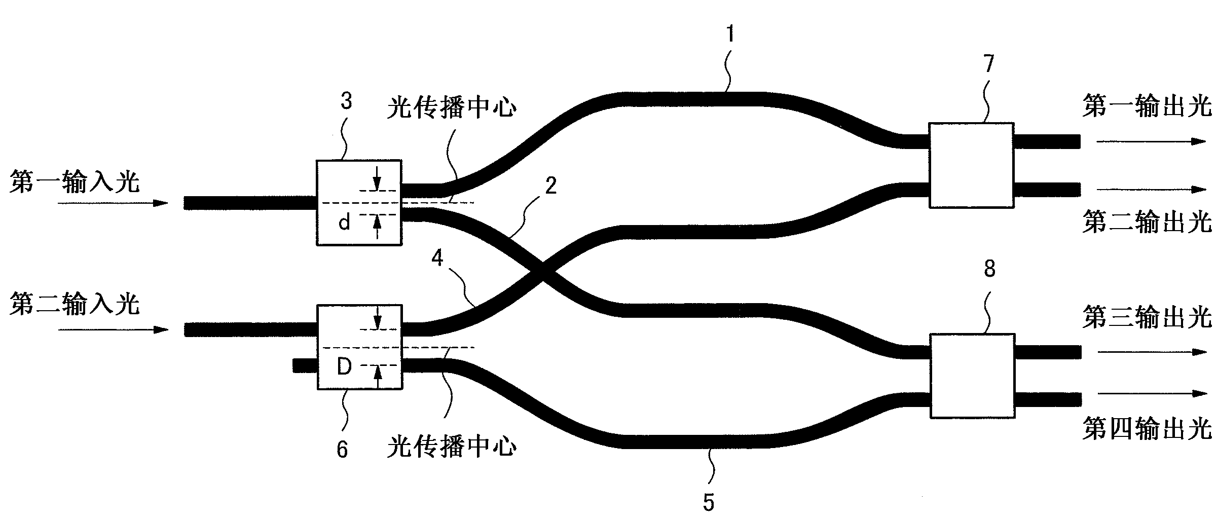
[0032] figure 1 is a schematic diagram showing the structure of the optical waveguide device according to the first embodiment of the present invention. figure 1 The optical waveguide device has: an optical branching device 3, which branches the first input light and outputs it to the optical waveguides 1 and 2; and an optical branching device 6, which branches the second input light and outputs it to the optical waveguides 4 and 5 . and figure 1The optical waveguide device has: an optical coupler 7 that mixes the light waves traveling through the optical waveguides 1 and 4, and then separates the mixed light waves to output first and second output lights; and an optical coupler 8 that mixes the light waves that pass through the optical waveguide 2 and 5 traveling light waves, and then separate and mix the light waves to output third and fourth output lights.

[0033] Each of the pair of optical waveguides 1 and 2 and the pair of optical waveguides 4 and 5 is equal in op...

no. 2 example )

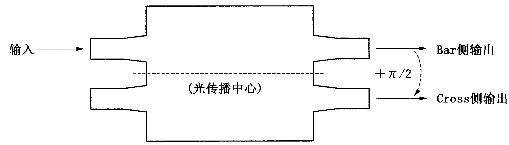
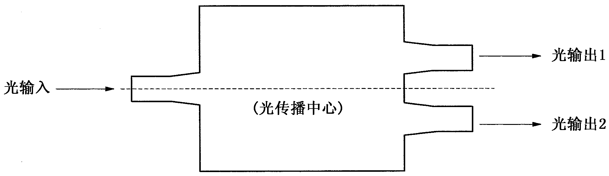
[0040] Next, a second embodiment of the present invention is described. The second embodiment uses the Y-branch structure type optical branching device as figure 1 Optical branching device 3 in. As the optical branching device 3, for example, even if using such as image 3 The shown multimode interferometer beam splitter with 1 input and 2 outputs having one input end performing light input from a position including the center of the light propagation direction can also perform the same light branching without causing a phase difference. However, the Y-branch structure type optical branching device has the characteristics that the structure is relatively simple, basically has no wavelength dependence, and is relatively resistant to interference in manufacture.

[0041] Also, as the optical couplers 7 and 8 , for example, Mach-Zehnder interferometers having the same characteristics can be used.

[0042] Furthermore, both the optical waveguide 1 and 2 pair, and the optical w...

no. 3 example )

[0053] Next, a third embodiment of the present invention is described. Figure 7 It is a schematic diagram showing an optical waveguide structure of a 90-degree optical mixing interferometer constituted by arranging two coherent mixers of the second embodiment in parallel.

[0054] However, in Figure 7 In , relative to the upper side coherent mixer, the lower side coherent mixer has an inverted positional relationship between the input ports of the optical signal and the local oscillator light. Therefore, the lower side coherent mixer switches the position of the input optical branching device, uses the Y-branch structure type optical branching device as the optical branching device 3b, and uses the 2-input and 2-output 3dB multimode interferometer beam splitter as the optical branching device 6b. In addition, the input side of the input light of the optical branching device 6b is also exchanged. Therefore, by configuring the lower side coherent mixer as described above, t...


PUM


Abstract

The present invention reduces the wavelength-dependency of the phase difference applied to optical waves propagating in optical waveguide arms constituting a coherent mixer. The optical waveguide device comprises a 3dB multimode interferometer splitter having: a first optical branching element which branches a first input light and outputs the same to a first and a second optical waveguide; a second optical branching element which branches a second input light and outputs the same to a third and a fourth optical waveguide; a first optocoupler which, after joining the light waves propagating in the first and third optical paths, branches the light to output a first and a second output light; and a second optocoupler which, after joining the light waves propagating in the second and fourth optical paths, branches the light to output a third and a fourth output light. The optical path length of the first and second optical waveguide pair is equal to the optical path length of the third and fourth optical waveguide pair. The first optical branching element has a structure whereby light is input from a position overlapping with the centre of optical propagation of the element. The second optical branching element has a structure whereby light is input from a position further towards the edge side than the centre of optical propagation of the element.

Description

[technical field] [0001] The present invention relates to optical waveguide devices, and more particularly to optical waveguide devices equipped with a phase delay function. [Background technique] [0002] In recent years, in the ultra-high-speed communication exceeding 100Gbit / s, attention has been paid to the polarization orthogonal multiplexing multi-valued digital signal modulation method (DP-QPSK:Dual Polarization Differential Quadrature Phase Shift Keying: Dual polarization differential quadrature phase shift keying) communication technology. For the receiver in the DP-QPSK system, the function of separating the polarized wave of the optical signal into a TE (Transverse Electric: Transverse Electric) optical signal and a TM (Transverse Magnetic: Transverse Magnetic) optical signal, and for performing polarization separation from A 90-degree optical mixing function is necessary to extract the phase signal from these optical signals. This phase information is quaternar...

Claims


Application Information

Patent Timeline
Patent Type & Authority Applications(China)
IPC IPC(8): G02B6/122
CPCG02B6/125G02B6/2813G02B6/126G02B2006/12061G02B2006/12159Y10T29/49826G02B6/29383G02B6/29395G02B6/2938G02B6/2821
Inventor 渡边真也
Owner NEC CORP
Why Eureka
Try Eureka