a fixed structure

A fixed structure and fixed groove technology, applied in the direction of clamping, positioning devices, supports, etc., can solve the problems that the pin holes cannot be processed in place at one time, the processing accuracy is not high, and the efficiency is low, so as to reduce the detection cost and respond quickly. cost saving effect

Active Publication Date: 2016-05-18
浙江佳鸿汽车科技股份有限公司
View PDF7 Cites 0 Cited by
  • Summary
  • Abstract
  • Description
  • Claims
  • Application Information

AI Technical Summary

Problems solved by technology

[0009] In view of the problems in the prior art that the pin holes of the base plate cannot be processed in place at one time, the efficiency is low, the processing accuracy is not high, and the repair rate is high, the present invention provides a fixing structure

Method used


Image

  • a fixed structure
  • a fixed structure
  • a fixed structure

Examples


Embodiment Construction

[0034] In order to understand the technical content of the present invention more clearly, the embodiments of the present invention will be further described in detail below with reference to the accompanying drawings.

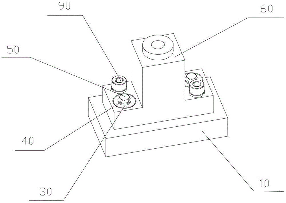
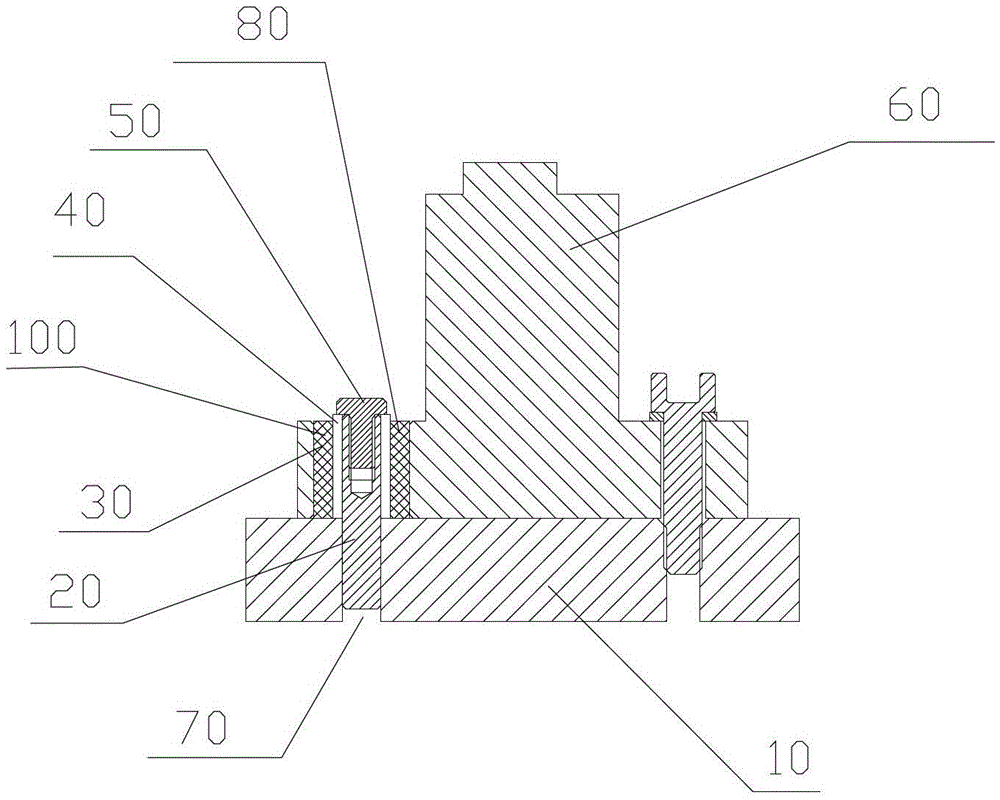
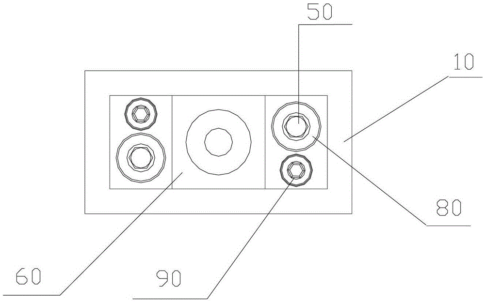
[0035] figure 1 According to the present invention, a schematic structural view of the fixing mechanism is shown, figure 2 shows a sectional view of the fixing mechanism according to the present invention, image 3 A top view of the fixing structure according to the present invention is shown. refer to figure 1 , figure 2 , image 3 , the fixing structure used for processing and fixing two workpieces includes a first workpiece 60, a second workpiece 10, a fastening bolt 90, a positioning pin 20, a colloid 30, a pin bushing 40, a pin cover screw 50, a positioning hole 70, and a fixing groove 80. Wherein, the fixing groove 80 is arranged on the first workpiece 60, the second workpiece 10 is provided with the same positioning hole 70 as the fixing groove ...


PUM


Abstract

The invention provides a fixing structure comprising fastening bolts for processing and fixing of two workpieces. The fixing structure further comprises a fixing socket reserved in a first workpiece, and a positioning hole which is communicated with the fixing socket and reserved in a second workpiece. A pin with a pin bushing is disposed in the positioning hole. The pin bushing is sleeved on the positioning pin. An accommodating space is reserved between the pin bushing and the inner wall of the fixing socket and is filled with glue. The fixing structure has the advantages that pin positioning precision is improved greatly, processing efficiency is improved, production cost, detection cost and labor cost are reduced, and the fixing structure is highly mobile and responds fast.

Description

technical field [0001] The invention relates to a fixing structure, in particular to a fixing structure fixed by positioning pins. Background technique [0002] At present, the fixing method commonly used in the equipment, tooling, fixture, jig, and inspection tool industry is: after fixing the two workpieces with screws, manually use drilling and milling equipment to process the positioning pin holes, and then use them as positioning pins. [0003] The existing technical solutions have the following disadvantages: [0004] 1. Due to the need for pin matching in the later stage, the pin holes of the base plate of a workpiece cannot be processed in place at one time, wasting time and inefficiency; [0005] 2. For the operation of the pin hole diameter and position of complex curved surface parts and large parts, the processing accuracy is not accurate, repeated processing and rework are frequent, resulting in low efficiency, which must be completed with high-precision equipm...

Claims


Application Information

Patent Timeline
Patent Type & Authority Patents(China)
IPC IPC(8): B23Q3/00
Inventor 王春华
Owner 浙江佳鸿汽车科技股份有限公司
Why Eureka
Try Eureka