Automatic stainless pan polishing equipment

A technology of automation equipment and stainless steel pots, applied in the direction of grinding/polishing equipment, metal processing equipment, surface polishing machine tools, etc., can solve the problems of high labor intensity, harm to human health, high cost, etc., to reduce production costs and labor The effect of improving strength and productivity

Inactive Publication Date: 2013-09-04
冯会民
View PDF8 Cites 28 Cited by
  • Summary
  • Abstract
  • Description
  • Claims
  • Application Information

AI Technical Summary

Problems solved by technology

However, there are many shortcomings in manual polishing: high labor intensity, low labor safety factor, high cost, low efficiency, difficult to control the working environment in the workshop, high quality and high scrap, great impact on the body of the operator and easy to get occupational diseases and serious injuries human health
At the same time, the technology of manual polishing mainly depends on the work experience of the polishing workers, the stability of the polishing quality is poor, and the product quality is uneven

Method used


Image

  • Automatic stainless pan polishing equipment
  • Automatic stainless pan polishing equipment
  • Automatic stainless pan polishing equipment

Examples


Embodiment 1

[0038] Embodiment 1: Surface polishing operation of stainless steel pot body

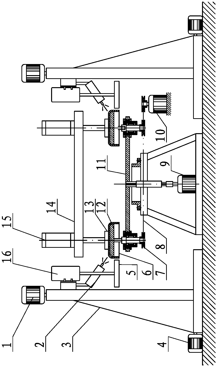
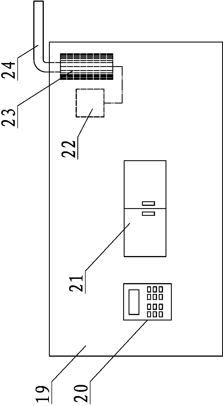
[0039] Such as figure 1 As shown, in this embodiment, the fixing fixture is installed on the workbench 11 through the rotating device; the workbench 11 is connected to the workbench motor 9, and can be driven to rotate by the workbench motor 9; the polishing device is installed on the support 3 through the moving device ; The electric control device 20 connects and controls the polishing device, the rotating device, the table motor 9 and the moving device.

[0040] The polishing device includes a polishing motor 16 and a polishing wheel 5 , the rotating shaft of the polishing motor 16 is connected to the polishing wheel 5 and can drive the polishing wheel 5 to rotate; the electric control device 20 is connected to and controls the polishing motor 16 . When the polishing device carried out the external throwing operation, the rotating shaft of the polishing motor 16 was vertically arranged, and the ...

Embodiment 2

[0049] Embodiment two: the inner surface polishing operation of the stainless steel pot body

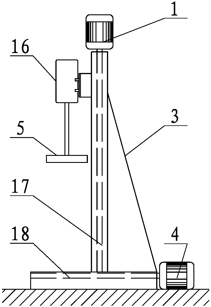
[0050] Such as Figure 4 Shown is the structural diagram of polishing the inner surface of the stainless steel pot body 6 in the present invention. When the polishing device carries out the internal throwing operation, the rotating shaft of the polishing motor 16 forms an angle of 0-90 degrees with the horizontal plane, and the polishing wheel 5 is attached to the inner surface of the stainless steel pot body 6 . Embodiment two differs from embodiment one in that:

[0051] Such as Figure 5 As shown, the polishing motor 16 is installed on the support 3 through the angle adjustment device 25 and the moving device. The angle adjusting device 25 includes a motor mounting plate 27 , the upper end of which is hinged on the support 3 , and the lower end of the motor mounting plate 27 is connected to the support 3 through an adjusting bolt 28 . The polishing motor 16 is mounted on a mot...


PUM


Abstract

The invention belongs to the technical field of polishing and particularly relates to automatic stainless pan polishing equipment. The automatic stainless pan polishing equipment is characterized in that the equipment comprises an electrical control device, a workbench, fixing clamps, supports and polishing devices, the fixing clamps are mounted on the workbench through a rotating device, the workbench is connected with a workbench motor and driven by the same to rotate, the polishing devices are mounted on the supports through a moving device, and the electrical control device is connected with and controls the polishing devices, the rotating device, the workbench motor and the moving device. The automatic stainless pan polishing equipment is reasonable in structural design and high in working efficiency, polished products are shining, dust pollution and damages to human bodies cannot be caused in the process of operating, labor intensity of workers is reduced, production cost is lowered, and a brand-new automatic polisher equipment capable of replacing manpower is provided.

Description

technical field [0001] The invention belongs to the field of polishing equipment, and in particular relates to automatic polishing equipment for stainless steel pots. Background technique [0002] In the process of manufacturing stainless steel pots, it is often necessary to polish the inside and outside of the pot body. Due to the complex shape of the pot body and the curve of the inner wall, the polishing process of the pot body is cumbersome and difficult to achieve automatic mechanical polishing, mainly relying on manual work. However, there are many shortcomings in manual polishing: high labor intensity, low labor safety factor, high cost, low efficiency, difficult to control the working environment in the workshop, high quality and high scrap, great impact on the body of the operator and easy to get occupational diseases and serious injuries human health. At the same time, the technology of manual polishing mainly depends on the work experience of the polishing work...

Claims


Application Information

Patent Timeline
Patent Type & Authority Applications(China)
IPC IPC(8): B24B29/02B24B41/06B24B55/06
Inventor 冯会民
Owner 冯会民
Why Eureka
Try Eureka