Washing machine capable of rubbing clothes

A washing machine and main motor technology, which can be applied to other washing machines, washing devices, energy and waste water treatment, etc., can solve the problems of inability to achieve rubbing, low efficiency, time-consuming and power-consuming, etc., to shorten the washing time, prevent environmental pollution, reduce load effect

Active Publication Date: 2013-09-04
桐乡佳车科技股份有限公司
View PDF4 Cites 2 Cited by
  • Summary
  • Abstract
  • Description
  • Claims
  • Application Information

AI Technical Summary

Problems solved by technology

[0003] Existing fully automatic washing machines only rely on the dial wheel to drive the clothes and the water flow to rotate in reverse repeatedly to achieve the purpose of cleaning, and cannot realize the function of rubbing
When dehydrating, the water is separated from the clothes only by high-speed rotation to generate centrifugal force. This method is time-consuming and power-consuming, and the efficiency is low.

Method used


Image

  • Washing machine capable of rubbing clothes
  • Washing machine capable of rubbing clothes
  • Washing machine capable of rubbing clothes

Examples


Embodiment 1)

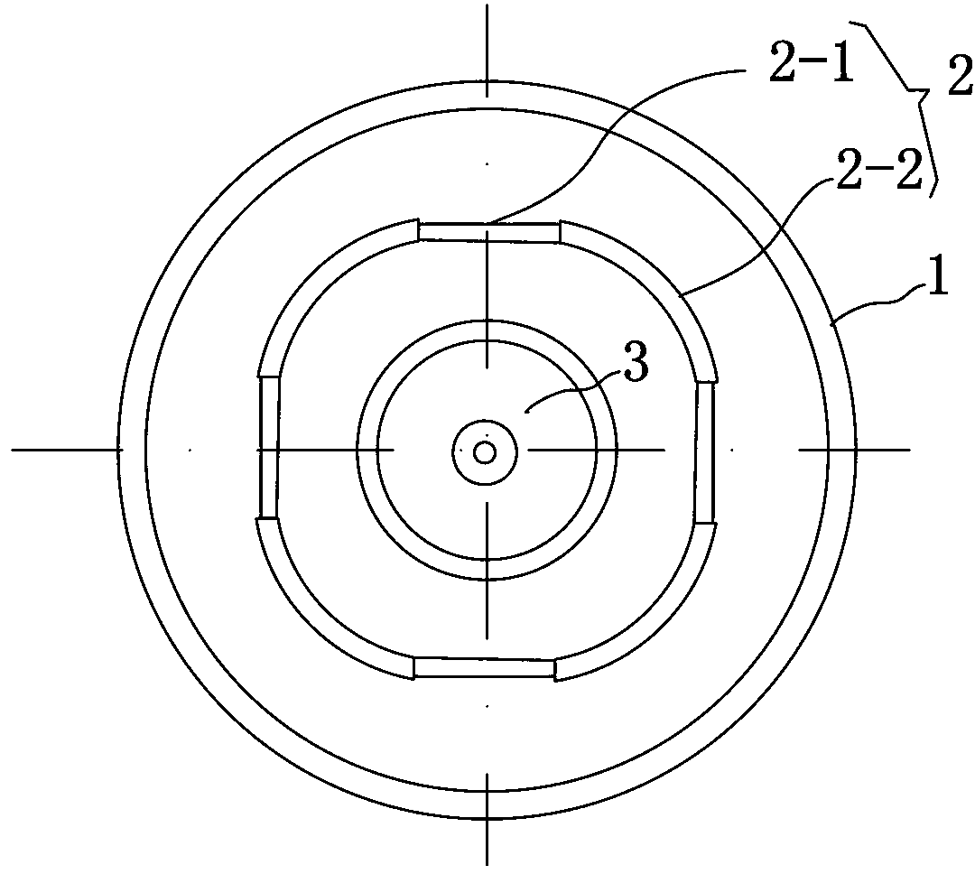
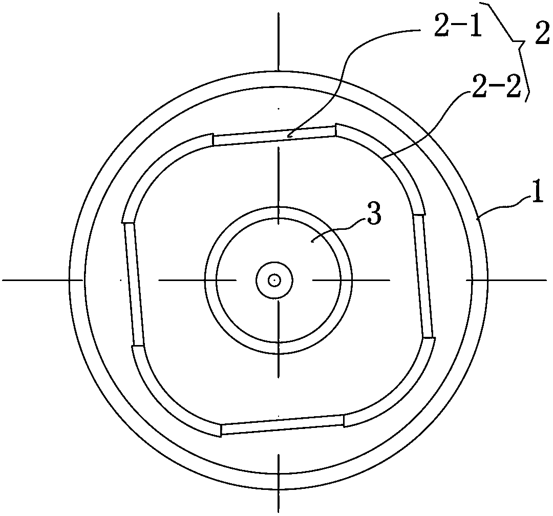
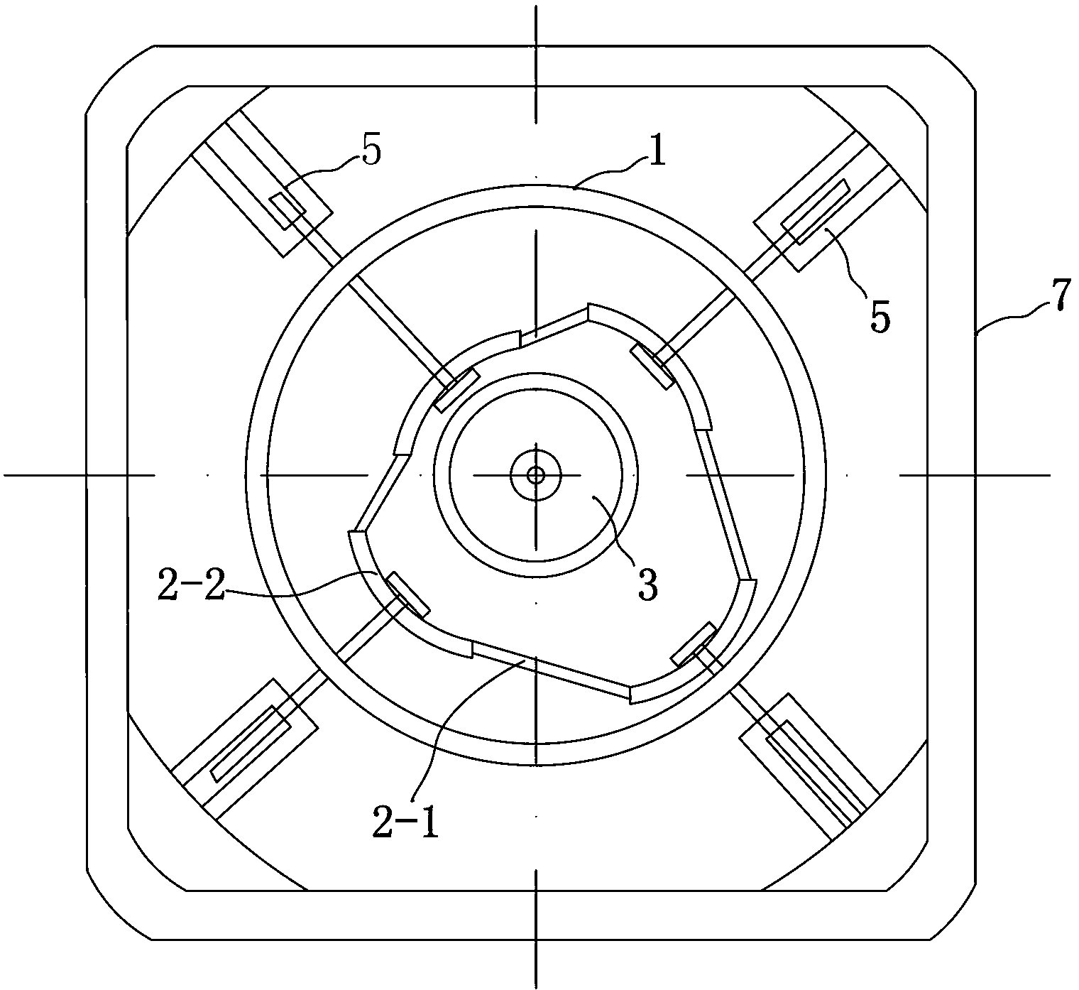
[0017] See Figure 1-5 , the washing machine of this embodiment comprises: an outer tub 1, an inner tub 2 arranged in the outer tub 1, and a dial 3 arranged in the inner tub 2; the dial 3 is driven by a main motor, and the output shaft of the main motor is connected with the The outer barrel 1 is connected to the inner barrel 2; the inner barrel 2 includes at least 2 pairs of elastic petals 2-1 and non-elastic petals 2-2 for connecting successively into barrels, and the walls of the non-elastic petals 2-2 are distributed with A through hole that is only open when the washing machine is performing a spin cycle.

[0018] Each non-elastic petal body 2-2 is distributed along the outer edge of the dial 3, and each non-elastic petal body 2-2 is connected with a connecting rod 5 for controlling its radial displacement, and the connecting rod 5 is connected with a driving mechanism; When performing the washing and rinsing procedures, with the rotation of the dial 3, the driving mecha...

Embodiment 2)

[0028] See Image 6 , apply the water treatment system of the washing machine in the above embodiment, comprising:

[0029] The water storage tank 21 is used to collect the waste water discharged from the washing machine;

[0030] Wastewater evaporating device 22 is used to be arranged on the air exhaust side of air conditioner outdoor unit 23 and connected to said water storage tank 21, so as to utilize the hot air discharged by air conditioner outdoor unit 23 to evaporate said waste water;

[0031] The waste water evaporating device 22 includes multi-layer evaporating pans 221 arranged up and down, and the waste water from the water storage tank 21 is directly discharged into the evaporating pan 221 on the top floor; There are water holes for introducing water into the lower layer.

[0032] Under the control of the solenoid valve connected to the drain pipeline 11 at the bottom of the outer tub 1, the water storage tank 21 only collects the waste water discharged when the ...


PUM


Abstract

The invention relates to a washing machine which comprises an outer barrel, an inner barrel arranged in the outer barrel and a poking wheel arranged in the inner barrel. The poking wheel is driven by a main motor, and an output shaft of the main motor is connected with the outer barrel and the inner barrel through an electronic clutch. The washing machine is characterized in that the inner barrel comprises at least two pairs of elastic petal bodies and non-elastic petal bodies which are sequentially connected to form a through body. Through holes opened only when the washing machine executes a dewatering program are distributed on the wall bodies of the non-elastic petal bodies. The non-elastic petal bodies are distributed along the outer edge of the poking wheel and connected with a connection rod used for controlling radial displacement of the non-elastic petal bodies, and the connection rod is connected with a driving mechanism. When the washing machine executes a washing or rinsing program, the driving mechanism controls the non-elastic petal bodies to move quickly and radially in a reciprocating mode through the connection rod along with rotating of the poking wheel.

Description

[0001] This application is a divisional application with the application number: 200910260565.2 and the filing date: December 10, 2009, and the name of the invention is "Washing Machine and Water Treatment System Using the Washing Machine". technical field [0002] The invention relates to a fully automatic washing machine. Background technique [0003] Existing fully automatic washing machines only rely on the dial wheel to drive the clothes and the water flow to rotate in reverse repeatedly to achieve the purpose of cleaning, and cannot realize the function of rubbing. When dehydrating, the water is separated from the clothes only by high-speed rotation to generate centrifugal force. This method is time-consuming and power-consuming, and the efficiency is low. Contents of the invention [0004] The technical problem to be solved by the present invention is to provide a washing machine capable of rubbing clothes during washing and rinsing. [0005] In order to solve the ...

Claims


Application Information

Patent Timeline
Patent Type & Authority Applications(China)
IPC IPC(8): D06F15/02D06F39/08
CPCY02B40/18Y02W10/37
Inventor 不公告发明人
Owner 桐乡佳车科技股份有限公司
Why Eureka
Try Eureka