
Castellated beam, concrete flitch beam and design method

A technology of composite slab beams and prefabricated concrete slabs, which is applied in the direction of joists, girders, truss beams, etc., can solve the problems of high structural heights that cannot meet the requirements, uneven floors under the floor, and large floor structure heights, etc., so as to facilitate layout Pipelines, on-site operations are convenient, and the surface of the floor is smooth

Active Publication Date: 2013-09-04
CENT RES INST OF BUILDING & CONSTR CO LTD MCC GRP +1
View PDF6 Cites 15 Cited by
  • Summary
  • Abstract
  • Description
  • Claims
  • Application Information

AI Technical Summary

Problems solved by technology

[0002] In the steel structure building, the floor structure mostly adopts the composite floor slab of profiled steel plate concrete. This floor system has the advantages of short construction period, convenient on-site operation, and the building integrity is better than that of the prefabricated floor. However, there are also high floor structures. , the lower surface of the floor is uneven and needs to be suspended, the bottom of the profiled steel plate needs to be treated with fire protection, and the cost of fire protection and anticorrosion is high.
In high-rise buildings, because of the equipment installation pipes on the top of the storey and the vertical and horizontal frame girders, a certain storey height is required. In the structural design of high-rise buildings, it is often necessary to reduce the beam height as much as possible due to storey height restrictions or increased net height requirements. Cross-sectional height, the traditional floor structure cannot meet the requirements due to its high structural height, and it is urgent to develop a new floor structure system in order to meet the engineering needs

Method used


Image

  • Castellated beam, concrete flitch beam and design method
  • Castellated beam, concrete flitch beam and design method
  • Castellated beam, concrete flitch beam and design method

Examples


Embodiment Construction

[0024] The present invention will be further described below in conjunction with the accompanying drawings.

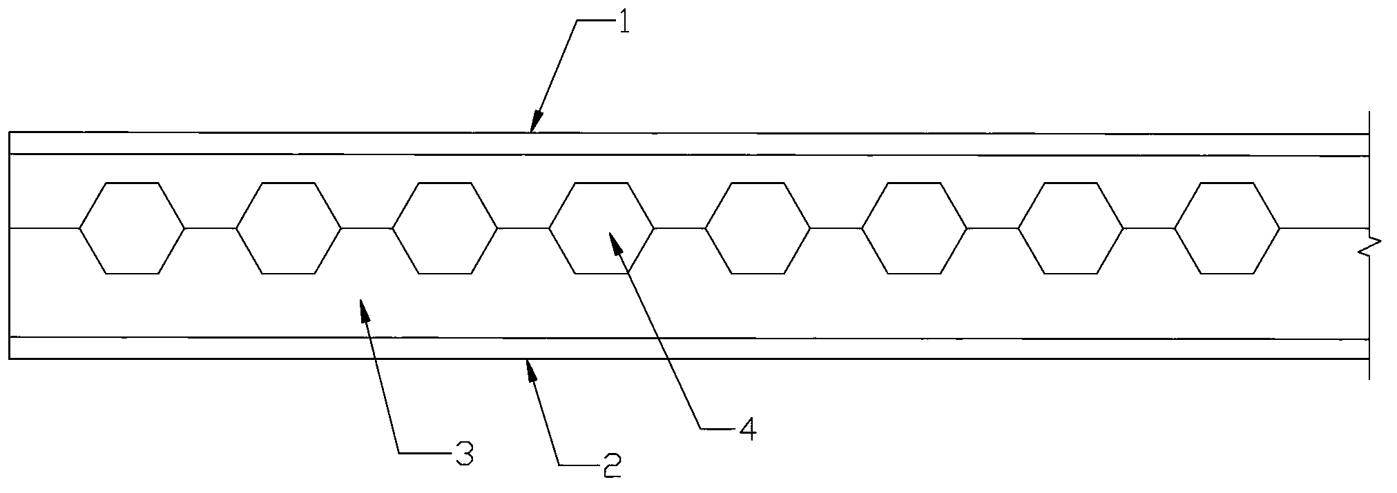
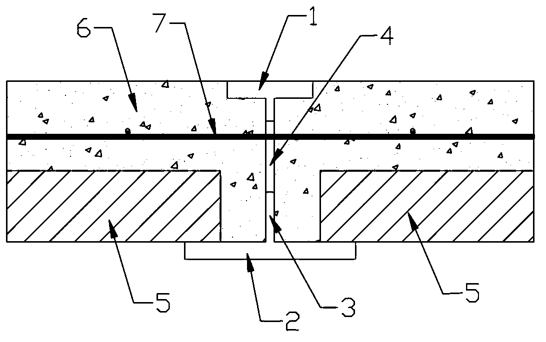
[0025] A honeycomb beam according to the embodiment of the present invention is composed of an upper flange plate 1, a lower flange plate 2, and a web 3 placed between the upper flange plate and the lower flange plate, and a Rows of evenly arranged honeycomb holes 4. The function of the honeycomb holes is to allow reinforcing steel bars to pass through during building construction, so as to provide convenience for construction layout.

[0026] Further explanation as the embodiment of the present invention:

[0027] The width of the upper flange plate is smaller than the width of the lower flange plate. The lower flange plate can be used to set up the precast concrete slab during construction. The web is a vertical single web, or a vertical double web, and there is a gap between the webs.

[0028] Such as figure 1 and figure 2 As shown, the honeycomb holes are re...


PUM


Abstract

The invention discloses a castellated beam, a concrete flitch beam and a design method. The concrete flitch beam at least comprises the castellated beam, precast concrete planks and cast-in-situ concrete composite layers, wherein the castellated beam comprises an upper flange plate, a lower flange plate and a web plate arranged between the upper flange plate and the lower flange plate; and a row of cellular holes are evenly formed in the web plate. The precast concrete planks are placed on two sides of the lower flange plate of the castellated beam respectively, and the upper parts of the precast concrete planks , the upper part of the castellated beam and a space defined by the upper flange plate, the lower flange plate and the web plate are covered with the cast-in-situ concrete composite layers. The castellated beam and the concrete flitch beam have the advantages that the construction period is short, the field operation is convenient, the building integrality is superior to a prefabricated floor, and the like.

Description

technical field [0001] The invention relates to the technical field of construction engineering, in particular to a honeycomb beam, a concrete composite plate beam and a design method. Background technique [0002] In the steel structure building, the floor structure mostly adopts the composite floor slab of profiled steel plate concrete. This floor system has the advantages of short construction period, convenient on-site operation, and the building integrity is better than that of the prefabricated floor. However, there are also high floor structures. , The lower surface of the floor is uneven and needs to be suspended, and the bottom of the profiled steel plate needs to be treated with fire prevention, and the cost of fire prevention and anticorrosion is high. In high-rise buildings, because of the equipment installation pipes on the top of the storey and the vertical and horizontal frame girders, a certain storey height is required. In the structural design of high-rise ...

Claims


Application Information

Patent Timeline
IPC IPC(8): E04C3/08E04C3/293
Inventor 陈水荣侯兆新龚超杨怡婷侯晓军
Owner CENT RES INST OF BUILDING & CONSTR CO LTD MCC GRP
Learn More