Magnetic Suspension Double Wind Wheel Wind Turbine

A wind turbine and magnetic levitation technology, which is applied to wind turbines, wind turbines in the same direction as the wind, and assembly of wind turbines, can solve the problems of poor economy, increased windward area of ​​the nacelle, and large structure, and achieves improved output power, The effect of reducing operating costs and reducing maintenance costs

Active Publication Date: 2016-03-02
SUZHOU YUNSHOU SOFTWARE TECH CO LTD
View PDF11 Cites 0 Cited by
  • Summary
  • Abstract
  • Description
  • Claims
  • Application Information

AI Technical Summary

Problems solved by technology

[0002] The wind energy utilization rate C of the current prior art wind power generator P Not high, Bezier limit is 0.593, this is just a theoretical value, the actual wind turbine C P It is only below 0.4, and more than half of the wind energy is not utilized. It is generally accepted that the wake energy of the incoming wind forms a spiral vortex after the wind rotor blades do work, and the energy is exhausted by itself.
At present, the unit power investment of wind turbines is relatively high but the output is low, so the economy is poor, and they still need to rely on government subsidies to operate
At present, there is a patent ZL201020639154.2 that uses front and rear wind rotors to increase the output of wind power generation, but its synthesis mechanism uses a conical gear differential gear train. The steering of the two input ends of the differential gear train is inconsistent with the output of the actual wind rotor. The synthesis mechanism adjusts the direction before the input, which makes the structure huge and difficult to implement. This patent synthesizes the movement of the front and rear wind rotors and uses column gears as output. The cylindrical solid tower has a great effect on the rear wind turbine tower
[0003] The natural incoming wind speed is changing. The wind rotor from the cut-in wind speed to the rated wind speed to the cut-out wind speed is the operation cycle of the wind turbine. During the operation cycle, the incoming wind speed is changing, and the best blade tip can only be reached after the rated speed The speed ratio can achieve the maximum wind energy utilization coefficient. However, after the incoming wind speed reaches the rated wind speed, it will increase. The kinetic energy of the wind is proportional to the cube of the incoming wind speed. When the wind speed doubles, the kinetic energy increases by 8 times. The existing technology The generator and wind rotor of the wind turbine are driven by a fixed speed ratio. The speed of the wind rotor is limited by the rated speed of the generator. It is impossible to obtain the best blade tip speed ratio as the speed of the incoming wind increases. Or variable-pitch control of the wind wheel, when running at the rated speed to the cut-out wind speed, the energy increased by the third power above the rated wind speed is discarded. It can be seen that a large part of the energy of the prior art wind generator is not used in the operation cycle. use
[0004] The existing patent ZL201010124102.6 wind power generation device has no self-locking variable-speed speed-up gearbox, has a speed-changing function, can make full use of the high-speed wind energy, and can make the wind turbine rotor run above the rated wind speed, and can make full use of high wind speed More power generation, but the high-altitude gearbox on the tower pole increases the number of transmission clutches and gears due to the speed change. These vulnerable parts will increase the maintenance amount of high-altitude components and increase maintenance costs.

Method used


Image

  • Magnetic Suspension Double Wind Wheel Wind Turbine
  • Magnetic Suspension Double Wind Wheel Wind Turbine
  • Magnetic Suspension Double Wind Wheel Wind Turbine

Examples


Embodiment Construction

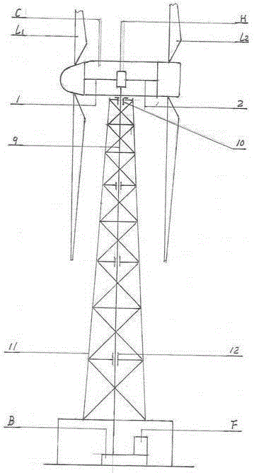
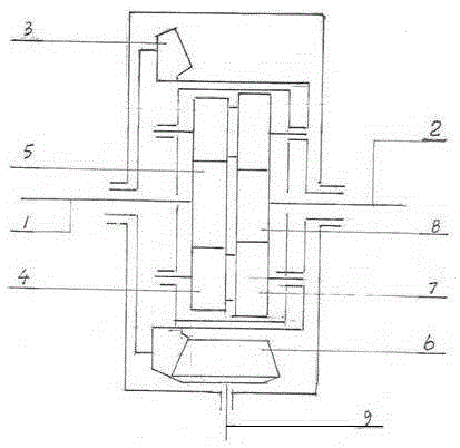
[0029] Accompanying drawing is a kind of specific embodiment of the present invention. This embodiment includes a nacelle C erected on the truss tower 11, and the two ends of the nacelle C are respectively equipped with front wind wheels L with the same parameters and opposite directions. 1 and rear wheel L 2 , front wind wheel L 1 and rear wheel L 2 The front wind wheel shaft 1 and the rear wind wheel shaft 2 are respectively connected to the mechanical synthesis mechanism H in the nacelle C, and the mechanical synthesis mechanism H is connected to the variable speed increaser box B at the bottom of the truss tower 11 through the magnetic levitation long axis 9, and the variable speed increaser box B is connected to Generator F; the top of the truss tower 11 is provided with a radial thrust magnetic suspension bearing 10 connected to the magnetic suspension long axis 9, and the inside of the truss tower 11 is provided with a radial magnetic suspension bearing 12 for fixing ...


PUM


Abstract

The invention relates to the technical field of new wind energies, in particular to a maglev twin-turbine wind generator comprising a cabin erected on a truss tower. The maglev twin-turbine wind generator is characterized in that front and rear wind turbines same in parameter and reverse in rotation direction are mounted at two ends of the cabin respectively. The front wind turbine and the rear wind turbine are connected with a mechanical composition mechanism inside the cabin through a front turbine shaft and a rear turbine shaft respectively. The mechanical composition mechanism is connected with a speed change gearbox at the bottom of the truss tower through a maglev long shaft, and the speed change gearbox is connected with a generator. Compared with the prior horizontal-shaft wind generator with the same windward area, the maglev twin-turbine wind generator has the advantages that increase proportionality coefficient of theoretical output power is 1.95, power generation is increased by 95%, manufacturing cost per KW of power generation is reduced greatly, and operating cost is also reduced.

Description

(1) Technical field [0001] The invention relates to the technical field of wind power generation new energy, in particular to a magnetic levitation double wind wheel wind power generator. (2) Background technology [0002] The wind energy utilization rate C of the current prior art wind power generator P Not high, Bezier limit is 0.593, this is just a theoretical value, the actual wind turbine C P It is only below 0.4, and more than half of the wind energy is not utilized. It is generally accepted that the wake energy of the incoming wind forms a spiral vortex after the wind rotor blades do work, and the energy is exhausted by itself. At present, the unit power investment of wind turbines is relatively high but the output is low, so the economy is poor, and they still need to rely on government subsidies for operation. At present, there is a patent ZL201020639154.2 that uses front and rear wind rotors to increase the output of wind power generation, but its synthesis mecha...

Claims


Application Information

Patent Timeline
Patent Type & Authority Patents(China)
IPC IPC(8): F03D1/02F03D13/10F03D15/00
CPCY02E10/72Y02P70/50
Inventor 岑益南
Owner SUZHOU YUNSHOU SOFTWARE TECH CO LTD
Why Eureka
Try Eureka