
Intelligent bolt for optical fiber grating sensor

A fiber grating and smart bolt technology, which is applied in the direction of optical devices, instruments, screws, etc., can solve the problems of multiplexing of white light interference sensors, the influence of ceramic core and optical fiber loss, and the inability to achieve single-point strain measurement. , to achieve the effect of easy distributed measurement, smart structure and low cost

Inactive Publication Date: 2013-09-04
BEIJING CHANGCHENG INST OF METROLOGY & MEASUREMENT AVIATION IND CORP OF CHINA
View PDF7 Cites 13 Cited by
  • Summary
  • Abstract
  • Description
  • Claims
  • Application Information

AI Technical Summary

Problems solved by technology

[0005] At present, a utility model patent "optical fiber smart bolt" has been retrieved. It is monitored based on the principle of white light interference sensing. The basic principle is that the reflected light and the reference light are coherent to generate interference fringes, and the strain information is reflected by the change of the interference fringes. , this sensing principle is sensitive to light transmission loss, and it is a light energy sensor; in this patent, the production of optical fiber white light interference deformation sensor is relatively complicated, and the connection and alignment of the ceramic core and optical fiber have a great influence on the loss of optical signals. The loss of energy directly affects the measurement accuracy of the sensor; the white light interference sensor is generally long, and generally measures the strain in the range of more than ten centimeters, and cannot achieve single-point strain measurement; the multiplexing of the white light interference sensor is difficult to achieve, and requires Modify the optical path of the sensing system according to the situation

Method used


Image

  • Intelligent bolt for optical fiber grating sensor

Examples


Embodiment

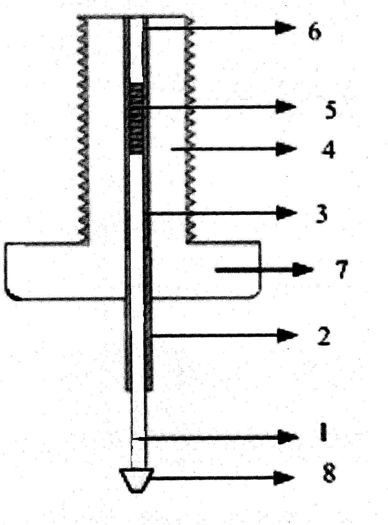
[0023] A smart bolt for a fiber grating sensor, the smart bolt includes a transmission fiber 1, a protective sleeve 2, an adhesive layer 3 and a bolt body 4, and the middle part of the transmission fiber 1 has a fiber grating sensor 5;

[0024] The material of the bolt body 4 is titanium alloy;

[0025] The material of the protective sleeve 2 is glass fiber;

[0026] The glue used in the adhesive layer 3 is epoxy glue;

[0027] The coating layer of the transmission optical fiber 1 is polyimide;

[0028] The top of the bolt body 4 has a bolt cap 7;

[0029] The bolt body 4 has a counterbore defined as the sensor embedding hole 6, the bottom of the bolt body 4 is blocked, and the top is a through hole;

[0030] The transmission optical fiber 1 is embedded in the bolt body 4 through the sensor embedding hole 6, and the fiber grating sensor 5 is also embedded in the bolt body 4;

[0031] The gap between the transmission optical fiber 1 and the sensor embedding hole 6 is filled...


PUM


Abstract

The invention relates to an intelligent bolt for an optical fiber grating sensor and relates to the optical fiber sensing and structure health monitoring field. According to the intelligent bolt, the optical fiber grating sensor is packaged in a bolt body and is used for monitoring, in an on-line mode, extension of the bolt body in a working state. The intelligent bolt comprises a transmission optical fiber, a protection sleeve, a rubber layer and the bolt body. The optical fiber grating sensor is arranged in the middle of the transmission optical fiber. A nut is arranged at the top end of the bolt body. The bolt body is provided with a countersink defined to be a sensor heeling-in hole. The bottom end of the bolt body is not through, and the top end of the bolt body is provided with a through hole. The intelligent bolt is simple in working principle, simple and convenient to manufacture, exquisite in structure, low in cost, and capable of achieving distribution type measurement easily, and effectively prevents large-scale structural pieces from causing accidents due to coming-off or breakage of bolts or other reasons.

Description

technical field [0001] The invention relates to an intelligent bolt used for a fiber grating sensor, which encapsulates the fiber grating sensor in the bolt and can be used for real-time online monitoring of the tension of the bolt under working conditions, and belongs to the field of optical fiber sensing and structural health monitoring. Background technique [0002] Bolts are the most important connectors in various large-scale equipment and engineering structures. They are widely used in engineering fields. Accidents caused by bolt looseness, fatigue and corrosion-induced fractures and overloads are often reported. These accidents have caused great damage. Economic losses and casualties; due to its special working state and structural characteristics, it is very difficult to realize real-time online working state monitoring. [0003] Fiber Bragg grating, referred to as fiber Bragg grating, is a wavelength modulation fiber sensor with a diameter of about 125 μm and a sens...

Claims


Application Information

Patent Timeline
IPC IPC(8): F16B35/00G01B11/16
Inventor 郭伟薛景锋宋昊刘春红
Owner BEIJING CHANGCHENG INST OF METROLOGY & MEASUREMENT AVIATION IND CORP OF CHINA
Learn More